Assemble the application basis
Start by defining the generating equipment and the facility it will serve. Application information commonly includes technology type, manufacturer and model, nameplate ratings, inverter or generator quantity, intended operating mode, and whether the system will export power. Include the facility service voltage, phase, utility account or service information requested by the utility, and a one-line diagram showing the proposed point of interconnection. Requirements vary by utility and project, so use the applicable Georgia utility forms and current instructions rather than assuming one application fits every territory.
Clarify whether generation operates in parallel with the grid, serves isolated loads, or uses controls to limit export. Identify energy storage, transfer equipment, multiple sources, and planned expansion because they can affect the application and protection review. For a quote, share the latest one-line, utility service details, equipment schedules, target operating modes, and any utility comments already received. Early alignment helps establish what the switchboard must contain and what information remains open.
Define the point of interconnection
The point of interconnection determines where generation joins the customer electrical system and which conductors, disconnecting means, metering provisions, and protective devices belong in the project scope. Review the service arrangement with the utility and the project engineer: connection at service equipment, a dedicated generation section, or another configuration can lead to different layouts and coordination needs. The switchboard drawings should identify source paths, bus sections, breakers, and the relationship between utility service and generation without obscuring normal and abnormal operating states.
Provide available service information and design criteria needed for equipment selection, such as system voltage, phase, frequency, bus requirements, and any utility-specified fault-current or device constraints. Do not infer interrupting ratings or protective-device settings from a preliminary application. The engineer of record must establish the design basis, while the utility confirms its applicable requirements. Our scope can be developed around that basis, with final configuration subject to approved drawings and confirmed equipment availability.
Prepare for protection review
Utilities review how a generating system responds to abnormal grid conditions and how it can be disconnected or prevented from energizing a de-energized utility circuit. Depending on the design and utility process, submittals may address protective functions, trip methods, visible isolation, anti-islanding behavior, relay or inverter settings, and coordination with service protection. The application package should make clear which functions are integral to listed generation equipment, which are provided by separate devices, and who is responsible for settings and testing.
Switchboard procurement should account for required breaker functions, control power, instrument transformers, relay compartments, terminal access, and wiring interfaces when those are part of the approved design. Confirm whether the utility expects review of equipment data, protection settings, witness testing, or commissioning records before parallel operation. These are project-specific decisions; a switchboard assembly does not by itself establish utility acceptance or determine whether the complete generating installation meets applicable requirements.
Coordinate metering and visibility
Metering can involve the utility revenue meter, a generation meter, production or export measurement, and customer monitoring. Establish which quantities the utility requires, where each meter or instrument transformer belongs, who furnishes the devices, and how access and wiring will be arranged. The utility may specify meter socket, cabinet, CT, or test-switch details, while the customer’s engineer defines other measurement needs. Resolve these interfaces before fabrication so the equipment layout can accommodate the actual requirements.
Share utility metering notes, service drawings, CT ratios or other approved instrument-transformer data when available, and any communications or telemetry requirements. Do not assume that the utility meter measures generation output or that customer monitoring satisfies utility data needs. Drawings should distinguish utility-furnished equipment from customer-furnished equipment and show boundaries, wiring responsibilities, and access provisions. Clarifying these points reduces field changes and helps the utility reviewer assess the intended arrangement.
Turn review comments into equipment scope
Treat utility approval as a sequence of documented decisions, not a single equipment submittal. The project team may need to submit an application, receive design conditions, revise drawings, provide equipment data, complete inspections or testing, and obtain permission to operate. Track comments by owner and revision, and keep the one-line, switchboard drawings, protection information, and metering details synchronized. A change in generator model, operating mode, or connection point can require renewed review.
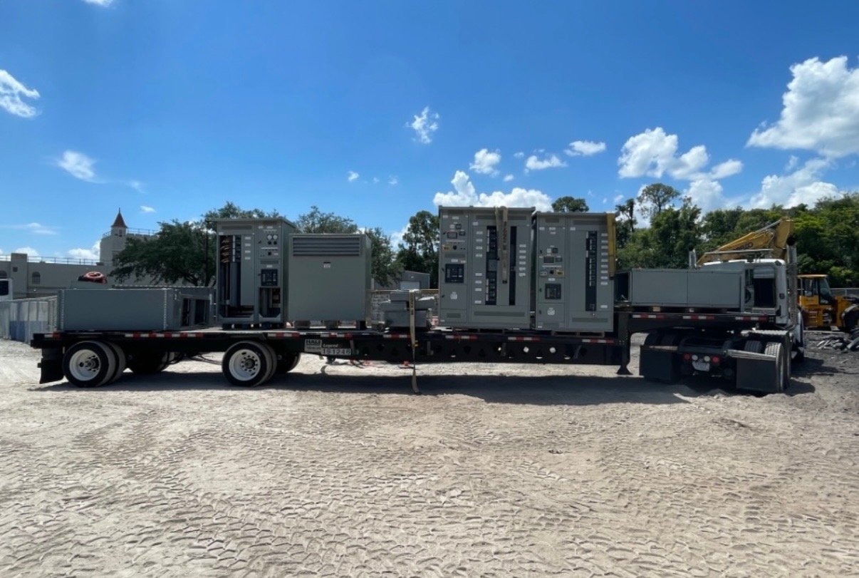
When requesting a switchboard quotation, provide the project location in Georgia, utility and service context, generation technology and ratings, intended export behavior, preliminary one-line, required metering interfaces, and known protection or enclosure constraints. Identify the drawing and approval milestones that affect release and delivery. We build new assemblies in the United States and can arrange nationwide shipping, including delivery to Georgia; configuration, availability, and schedule are confirmed for each order.
Close the handoff before energization
Before equipment release, compare the approved interconnection documents with the final equipment drawings and identify unresolved utility conditions. Confirm who will provide settings, perform field wiring, conduct required tests, coordinate inspection, and submit closeout records. Installation, testing, and energization must be handled by qualified personnel under the project’s engineering direction and applicable utility requirements. The authority having jurisdiction and utility determine their respective review and approval requirements.
A practical next step is to assemble the current utility application, one-line diagram, service data, generation equipment information, and reviewer comments into one project package. Mark confirmed requirements separately from assumptions, then request a switchboard scope review against that package. This gives the engineer, utility reviewer, contractor, and purchasing team a shared basis for resolving protection, metering, and delivery decisions before fabrication.