Start with the assembly interfaces
A welded frame must suit the complete assembly, not just its outer dimensions. Drawings should establish overall width, height and depth, section breaks, access openings, mounting surfaces, and the locations of doors, barriers and internal supports. Floor or base interfaces also matter: anchor patterns, leveling provisions and cable-entry areas can affect how the frame is laid out and how the finished equipment meets the installation plan.
Before requesting a quote, identify the equipment type and intended arrangement, including lineup direction, compartment sequence and whether the frame is for a single section or a connected lineup. Share available elevations, plan views, interface drawings and revision status. If final dimensions are still under engineering review, mark assumptions clearly so the frame scope can be evaluated without treating preliminary information as approved fabrication data.
Define material and fabrication requirements
Specify the intended frame material and finish requirements, along with any project standards that affect fabrication. Material thickness, formed members, weld locations and surface preparation influence stiffness, fabrication sequence and the space available for internal equipment. Where the frame will be joined to adjacent sections, define whether connections are welded, bolted or handled through another approved detail; the selected method should follow the project drawings and engineering review.
The frame must accommodate the actual equipment and service clearances, including bus supports, barriers, cable routing, lifting provisions and access for assembly. These features should be coordinated before fabrication rather than added by assumption. The manufacturer can review the supplied design information and confirm the scope that can be built; changes to geometry, material or finish after release may affect fit, work sequence and schedule.
Control squareness and alignment
Welding can introduce heat distortion, so a frame’s accuracy depends on more than cutting parts to nominal size. Fabrication planning may use controlled fit-up, suitable sequencing and fixtures to limit movement as joints are completed. Reference points and datums should be identified on the drawings where they govern door openings, section-to-section connections, mounting planes or equipment clearances. These references give inspection a consistent basis for checking the fabricated structure.
Useful alignment checks include overall dimensions, diagonals, flatness or coplanarity of mounting surfaces, and the position of openings and connection features. The relevant tolerances must come from approved drawings or project requirements; they should not be inferred from a general description of the equipment. If a lineup must mate with existing structures or site-installed interfaces, provide those verified dimensions and identify who is responsible for confirming the field conditions.
Plan inspection around the build
Inspection should verify the characteristics that determine whether the frame can accept its intended components and connect as designed. A project may call for dimensional checks at defined fabrication stages, visual examination of welds, confirmation of material documentation, or records for specified characteristics. Acceptance criteria and any required inspection documentation should be agreed before work begins, with responsibility and review points stated in the purchase documents.
Do not assume that a particular weld examination, tolerance, record package or third-party inspection is included unless it is specified and confirmed for the order. If a customer or engineer needs a witness point, hold point or approval before the next operation, identify it early enough to coordinate the sequence. Clear inspection criteria help resolve discrepancies against the approved design rather than relying on subjective judgments after the frame has advanced through assembly.
Coordinate frame scope with the finished assembly
A structural frame is only one part of the finished switchgear package. Confirm whether the requested scope includes enclosure panels, doors, internal mounting structures, bus supports, wiring provisions or other fabricated parts, and distinguish those items from the frame itself. For switchboard projects, UL 891 applies to switchboard assemblies; it should not be treated as a blanket certification for other switchgear types or as proof that an individual welded frame is independently listed.
Engineering review should reconcile frame drawings with the electrical arrangement, equipment dimensions and installation requirements before fabrication release. The customer and manufacturer should identify the controlling drawing revision, submittal status, permitted substitutions and the process for approving changes. That discipline reduces the risk of a frame that is structurally sound but incompatible with the specified assembly or site interface.
Prepare a clear Georgia project handoff
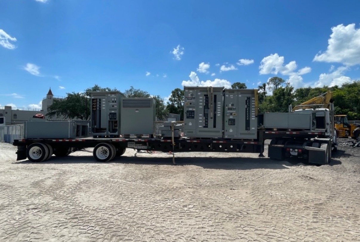
For a Georgia project quote, provide the required equipment type, lineup layout, approved or preliminary frame drawings, material and finish expectations, interface dimensions, inspection requirements and desired project milestones. Include delivery location, receiving limitations, unloading arrangements and whether sections need to arrive in a particular sequence. These details let the manufacturer assess fabrication scope and shipping coordination without assuming site access, installation conditions or a delivery commitment.
Before approving fabrication, ask which dimensions and tolerances will be verified, what inspection records are available for the agreed scope, and how drawing changes will be handled. Confirm the final configuration, revision and shipping plan in the order documents; availability and timeline are confirmed for each order. Send the frame requirements with the assembly drawings and site-interface information so engineering and procurement can resolve open items before release.