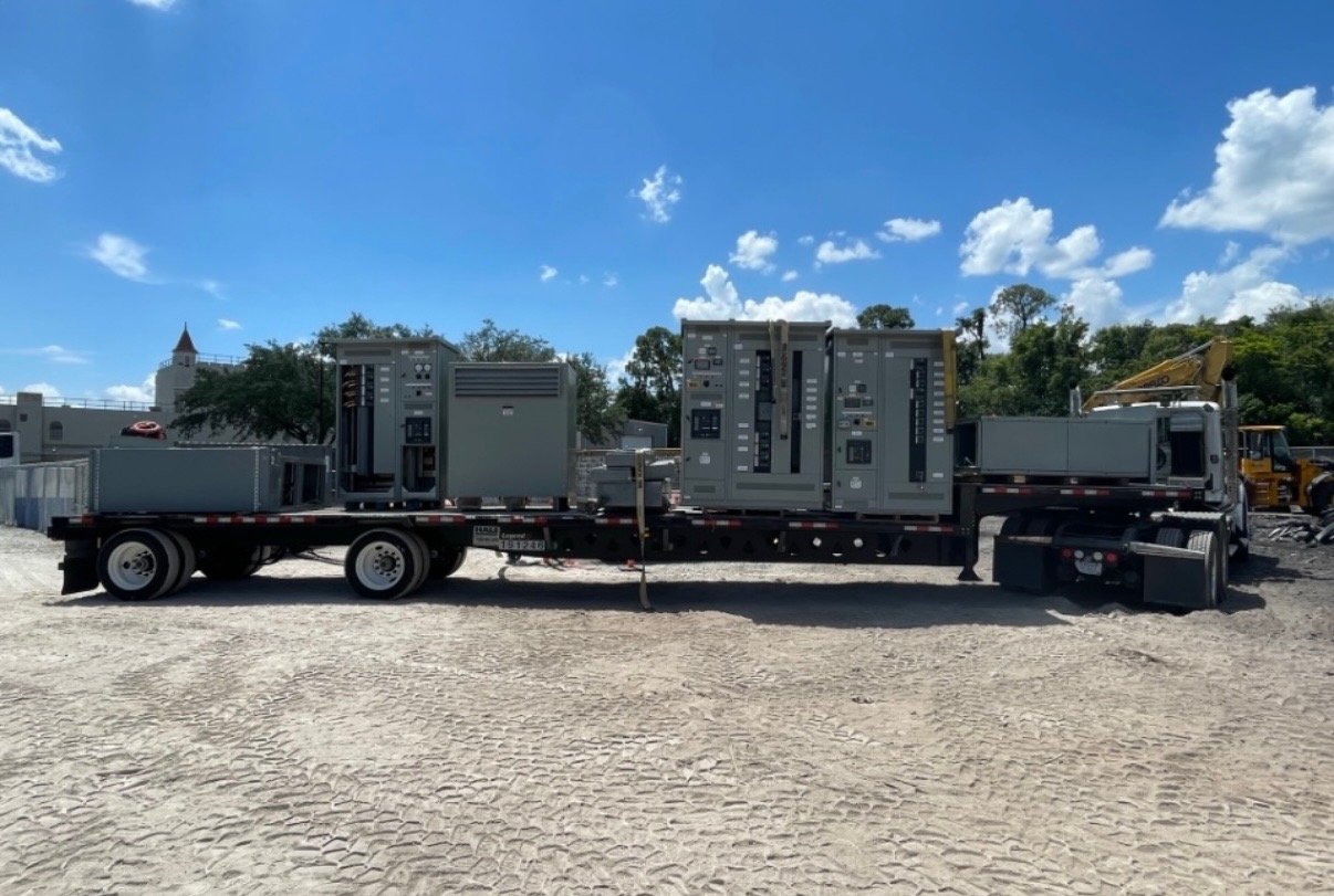
Define the replacement boundary
Begin with the operational problem and the equipment that must be replaced, rather than assuming that a similarly named product will fit. A retrofit may involve a new switchboard, a new switchgear lineup, or a replacement section designed around defined interfaces. Compare the condition and remaining useful life of retained equipment with the cost, outage implications and future needs of a broader replacement. A narrow boundary does not eliminate weaknesses in equipment left in service.
The owner’s qualified project team should identify the affected circuits, the functions that must continue, and the upstream and downstream equipment that will remain. Record the existing manufacturer, model, nameplate data, drawings and known modifications. Photographs provide context but do not establish dimensions, condition or ratings. Field inspection and measurements belong to qualified project parties working under the facility’s safety procedures; their verified information forms the basis of the new equipment specification.
Specify electrical duty and protection
The new assembly must suit the actual system, not merely match an old nameplate. Specify nominal voltage, phase, frequency, grounding configuration, continuous current, service conditions and the required number and ratings of main, tie and feeder devices. Provide available short-circuit current and the applicable short-circuit withstand or interrupting requirements at the installation point. Device interrupting ratings and assembly short-circuit ratings serve different purposes, and both must be appropriate for the proposed system.
A qualified electrical engineer should review protection functions, source and load information, and coordination with retained upstream and downstream devices. Changes in transformers, generators, motors or utility supply can affect fault duty and settings. Include requirements for metering, control power, interlocks and alarms in the order documents. An old setting or familiar breaker appearance is not proof that a new arrangement is compatible or correctly coordinated.
Resolve physical and retained-equipment interfaces
A new assembly needs a practical path into the building and a defined connection to the existing system. The project team should verify available footprint and working clearances, delivery access, ceiling height, cable or conduit entry, conductor termination space, grounding connections and environmental conditions. For a section interfacing with retained gear, document bus material and geometry, phase sequence, connection locations, barriers, structural supports and tolerances. Existing drawings may not reflect changes made after the original installation.
Provide verified interface information with the request for a new replacement. The responsible engineer and other applicable parties must evaluate the design, the condition of retained equipment, and any effect on the existing assembly’s listing or labeling. Confirm requirements with the authority having jurisdiction and the original equipment manufacturer where applicable. A proposed interface or matching dimension alone does not guarantee interchangeability, approval or suitability for connection to an older lineup.
Build and document the new equipment
We manufacture and supply new replacement equipment to an agreed configuration and scope; the project may call for a complete lineup or, where feasible and approved, a new section. Submittals can identify the proposed arrangement, equipment ratings, devices and connection details for project review before release to manufacture. Clarify the scope of factory inspection and production testing in the order and distinguish those activities from site acceptance testing.
Select the equipment class and applicable standards for the actual application. UL 891 addresses switchboards; it is not a blanket listing for medium- or high-voltage switchgear. Where a listed or labeled assembly is required, verify that the specific proposed assembly, manufacturer and configuration meet the project’s requirements rather than assuming that every custom arrangement qualifies. Confirm any special documentation, witness requirements and deviations in the written order.
Coordinate delivery and qualified field work
The owner’s qualified project parties plan and perform field inspection, removal, installation, modifications, maintenance, field testing, commissioning and energization. They establish isolation and an electrically safe work condition, follow the facility’s procedures and approved plans, and coordinate any utility or authority involvement. Those activities are separate from our manufacture and supply of new equipment; delivery does not include field services.
Align the build and delivery schedule with the project team’s outage plan and site readiness. The receiving party should confirm unloading equipment, shipping splits, storage conditions, rigging routes and contractor availability. Identify temporary supply arrangements and critical loads early so the responsible parties can plan the cutover. Manufacturing lead time, delivery date and any logistics scope depend on the confirmed order, not on a general estimate.
Prepare the retrofit equipment request
Share a current one-line diagram, equipment schedules, verified nameplate information, available fault-current data, applicable studies, required device functions and a clear description of the replacement boundary. Include verified dimensions and connection details, available photographs, environmental conditions, applicable standards, site location and the requested delivery window. Mark missing information and design assumptions so the responsible engineer can resolve them before the configuration is finalized.
Identify who will review drawings, who owns each retained interface and which documents are needed for handoff. After qualified contractors complete the field work, the project team should retain as-built drawings, field test records, protection settings and operating and maintenance documentation. That record supports future work and keeps the new equipment specification connected to the actual installed system.