Define the measurement objective
Start by listing the circuits or sources to be monitored and the decisions the readings must support. A facility may need total incoming demand, individual feeder current, voltage, energy consumption, power quality indicators or equipment status. These goals determine the number and type of measurement points, meter functions, display needs and data retention requirements. Avoid specifying a meter solely by display size or a familiar model number.
Clarify whether readings are for local observation, supervisory monitoring, billing allocation or operational analysis. Those uses can call for different accuracy, communications, reporting and data ownership requirements. Identify who will use the information, where it must be available and whether the project needs alarms or historical trends. The intended use helps engineering evaluate an appropriate configuration without assuming that existing switchgear has spare capacity or suitable provisions.
Document the existing assembly
Gather available one-line diagrams, switchgear nameplates, panel schedules, control drawings and prior modification records. Record manufacturer and model information, assembly voltage and current ratings, compartment layouts, available spaces, instrument transformer details and existing control power sources when known. Photographs of nameplates, meter locations, wiring paths and accessible interior labels can help clarify the scope, but should be taken only by qualified personnel following site safety procedures.
Existing drawings may be incomplete or may not reflect field changes. Engineering review must verify the actual arrangement before deciding whether meters can be added, existing devices can be replaced or a separate enclosure is needed. Space, heat, wiring routes, clearances and isolation provisions may constrain the work. Do not assume a meter’s physical fit or electrical compatibility from a similar installation; confirm the relevant equipment and interface details.
Specify sensors, inputs and wiring
For each measurement point, describe the source circuit and the quantities required. Current sensing may use existing current transformers, new transformers or another approved sensor arrangement, depending on the assembly and engineering design. Voltage inputs require their own review of source, fusing, reference and isolation. Provide known transformer ratios, secondary ratings and wiring diagrams, and flag missing or uncertain information rather than treating it as established.
Meter input limits, sensor output, polarity, phase association and grounding practices must align. Wiring plans should address conductor routing, terminal space, segregation from power conductors where required, labeling and access for testing or future replacement. If existing instrument transformers serve protection or other functions, adding a meter can affect connected circuits and burden; qualified engineering review is essential before changing those connections.
Plan communications and integration
Identify the data destination before selecting communications hardware. Share the facility’s preferred protocol, network architecture, connection method, required points, addressing approach and any cybersecurity or access requirements. Confirm whether the meter must communicate with an existing building management or energy management system, a local gateway or another approved platform. Compatibility depends on both device capability and the receiving system’s configuration.
Decide who will furnish and configure network connections, gateways, software and integration testing. The meter may provide data that still requires mapping, scaling, time synchronization or site-specific setup before operators can use it. Include desired registers or data points and clarify whether local display and remote access are both needed. Do not assume existing network cabling, control power or software licenses are available.
Coordinate procurement and project execution
A useful quote request includes the equipment nameplate information, one-line diagram, available drawings, photographs, measurement objectives, circuit count, known sensor data, communications requirements and delivery destination in Georgia. Note whether the scope is a new switchboard assembly, a replacement meter package or a planned upgrade to existing equipment. State which parts of the design are verified and which require investigation, along with site access and outage constraints.
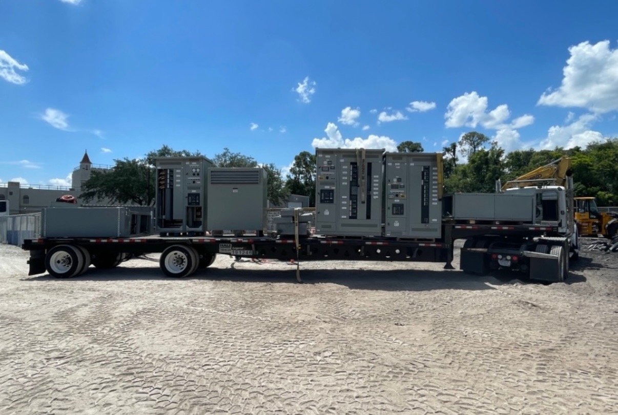
We manufacture and supply new switchgear and custom-built configurations using American-made components, with nationwide shipping. For a metering scope, the proposed equipment, interfaces, availability and schedule depend on engineering review and the specific order. Share the required submittal documents, labeling conventions, testing expectations and division of work between equipment supply and field installation so procurement and the project team can evaluate scope consistently.
Close the handoff with verified details
Before release for construction, align the approved drawings with meter models, sensor ratios, wiring diagrams, communications points and equipment labels. Resolve discrepancies between field conditions and documents before installation. Qualified electrical personnel should perform installation, testing and energization under the project’s approved procedures and applicable engineering and authority review; equipment supply alone does not establish that an existing assembly can accept a modification.
To begin planning, send the available switchgear records, a list of desired measurements, known instrument transformer information, communications destination and Georgia delivery requirements. Identify uncertainties and any outage window or procurement milestone. These details give engineering and purchasing a practical basis to confirm the proposed scope, identify compatibility questions and define the equipment handoff without presuming existing capacity.