Start with the protection scheme
Before selecting a replacement relay, establish what the existing device protects and how it operates within the larger scheme. Gather one-line diagrams, elementary or schematic drawings, panel layouts, relay model and function information, and available coordination or settings files. Note protective functions, alarm points, communications, interlocks, and any logic shared with other devices. These records help distinguish a direct functional replacement from a redesign that needs engineering review.
Document the equipment condition and project boundary as well. Is the relay being replaced in an existing switchboard, incorporated into a new assembly, or supplied as part of a broader switchgear modernization? Identify which components remain, which are being changed, and who is responsible for protection studies, field verification, installation, testing, and commissioning. A clear boundary helps procurement compare proposals on equivalent scope instead of assuming that a relay alone resolves every interface.
Verify CT and VT interfaces
Current transformer and voltage transformer connections must be checked against the proposed relay inputs. Share transformer ratios, secondary ratings, polarity and terminal references, grounding arrangement, phase designations, and any residual or neutral connections shown in the drawings. Confirm whether voltage is supplied phase-to-phase, phase-to-ground, or through another arrangement, and identify the intended connection for each protective function. The relay's input requirements and the actual circuit must be evaluated together.
Do not assume that matching nominal ratings makes the interface interchangeable. Existing wiring may include test switches, shorting blocks, fuses, or terminal arrangements that affect how the replacement is connected and tested. Obtain current drawings and have qualified electrical and protection personnel verify the installed circuit before finalizing the design. If records are incomplete, state what is known and what must be confirmed in the field; unresolved transformer or wiring details can affect scope, schedule, and the final configuration.
Carry trip logic forward deliberately
Record how a protection decision becomes a breaker trip. Identify trip coil circuits, lockout relays, breaker-failure functions, permissives, blocking inputs, reclosing logic, and alarm or indication outputs where applicable. Note whether the relay operates directly or through auxiliary devices, and document contact requirements and terminal assignments. A new relay may implement familiar protective functions differently, so logic diagrams and an input/output list are more useful than relying on device labels alone.
Preserving behavior does not mean copying every legacy setting or logic choice without review. Protection engineers should assess whether the existing scheme remains appropriate for the equipment and system, then define approved functions, logic, and trip outputs for the new design. Identify required communications or remote indications and whether existing protocols and point lists must be retained. Any change to protection, control, or interlocking should be explicit, reviewed, and recorded rather than introduced as an undocumented substitution.
Define settings and test records
Treat settings as controlled engineering information. Provide the latest approved settings file, printed setting sheets, revision history, and any available coordination study or basis for key values. Record relay firmware or configuration details when known, as well as enabled functions, pickup values, time delays, curves, logic equations, and communications parameters relevant to the application. If settings are uncertain or conflicting across records, flag the discrepancy for resolution rather than selecting a value by assumption.
For procurement, specify what documentation is expected with the equipment: final schematics, terminal plans, relay configuration files, settings records, and applicable factory test documentation. Define who approves settings and who performs field testing and commissioning. A useful handoff lets the installing and commissioning teams trace each CT and VT circuit, verify trip paths, compare loaded settings with the approved record, and capture final revisions. Test methods and acceptance criteria should be established by the responsible engineering team for the specific system.
Scope the assembly and delivery
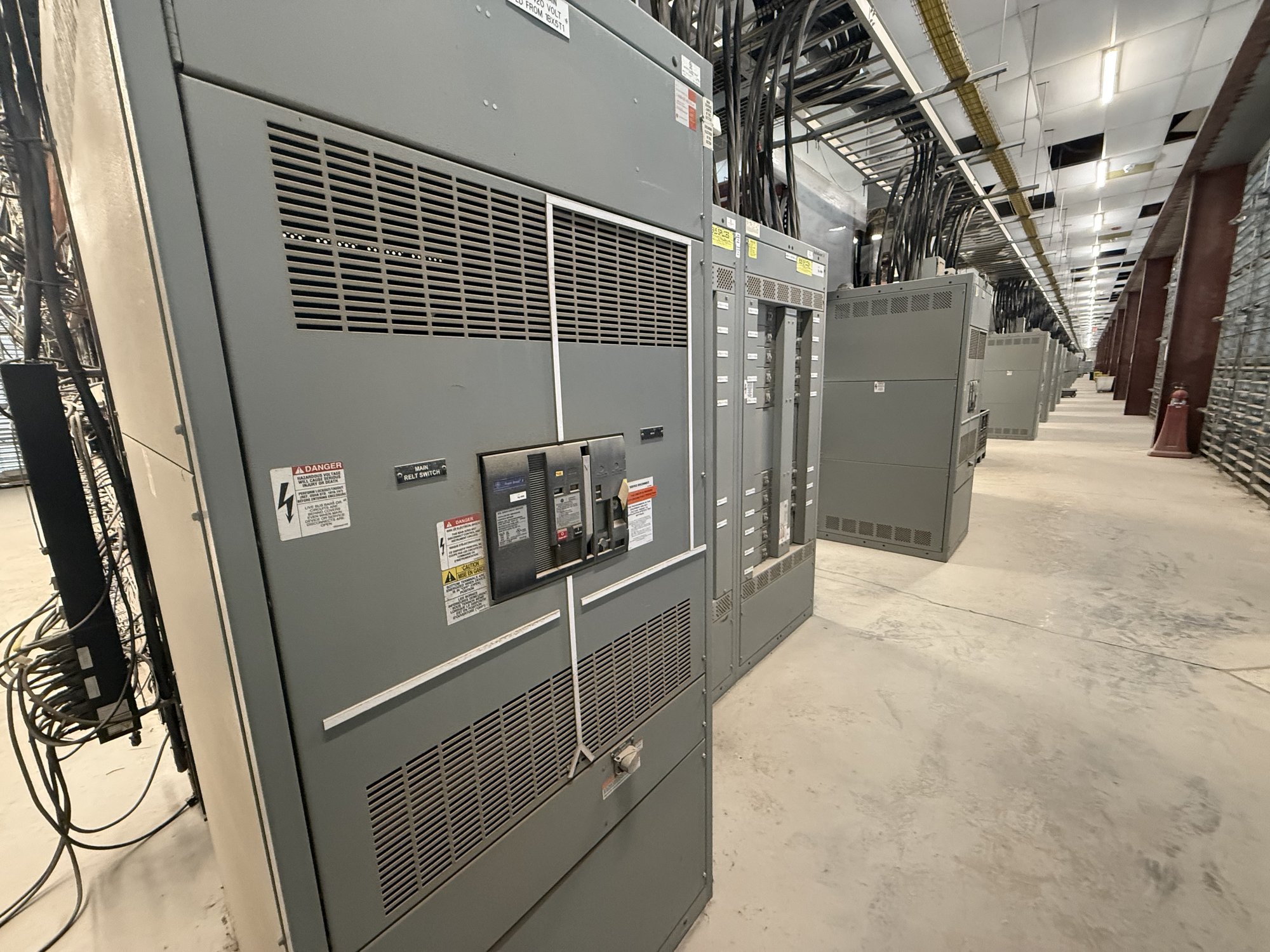
For a quote, share the switchboard or switchgear manufacturer and model if known, photographs or drawings of the relay compartment, available dimensions, nameplate information, system voltage, CT and VT data, breaker and trip details, and the intended replacement boundary. Include the quantity of relays, required functions, communications needs, drawing set, approved settings availability, and target project milestones. State whether the request is for a new custom-built assembly, a replacement section, or another defined equipment scope. These details support a practical review without presuming compatibility.
We manufacture and supply new electrical equipment in the United States, including custom-built configurations and UL 891 switchboard assemblies where applicable. UL 891 applies to switchboards; it should not be treated as a blanket listing for medium- or high-voltage switchgear. For Georgia projects, nationwide shipping can be coordinated to the project destination and receiving requirements. Confirm the exact scope, component availability, configuration, and timeline for each order, especially when relay interfaces depend on existing equipment records or engineering decisions.
Make the handoff verifiable
Before release for construction or installation, align the approved drawings, relay schedule, settings revision, and responsibility matrix. Resolve open items for CT and VT wiring, trip outputs, external logic, and field verification. Specify how drawing changes and settings updates will be controlled, and identify the records required at project closeout. This reduces the risk that procurement documents describe one arrangement while installation or commissioning proceeds from another.
For a Georgia relay modernization inquiry, send the available one-line and elementary drawings, relay and transformer data, settings records, and a concise description of what must remain unchanged. Mark unknowns rather than filling gaps by assumption, and identify the engineer responsible for approving protection changes. With that information, the equipment scope can be reviewed around the actual interfaces and handoff needs, with order-specific configuration and delivery details confirmed before commitment.