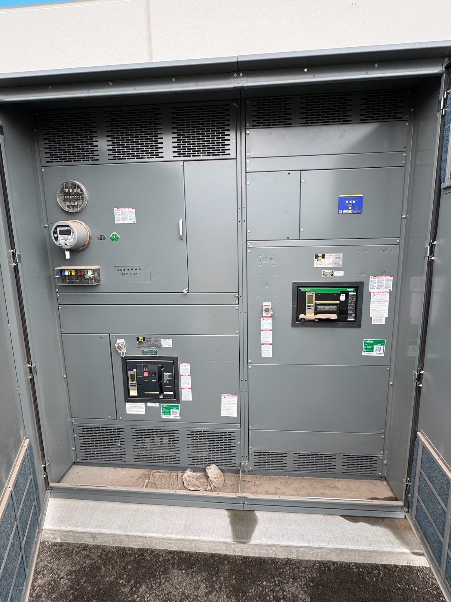
Start with the feeder schedule
The one-line diagram and feeder schedule establish what the section must contain. Identify each outgoing circuit, its destination, the required protective device type and frame or switch size, and any project-specific control or monitoring provisions. Confirm system voltage, phase, frequency, available fault-current information, and the equipment ratings established by the project engineer. These details affect the section layout and cannot be inferred from feeder count alone.
A schedule with many small feeders can call for a different arrangement than a few large feeders, even when the total number of circuits is similar. Share the latest one-line, load information, device descriptions, and required section grouping for quotation. If the schedule is still developing, identify which values are confirmed and which are pending so the proposed configuration can be reviewed against the expected design rather than treated as final.
Choose device capacity and arrangement
Feeder devices may be arranged as circuit breakers or switches, depending on the design, protection scheme, operating needs, and project specifications. Their size and construction influence how many devices fit, how they are accessed, and how conductors route to their terminals. A feeder-section layout should therefore be developed around the specified devices and clearances, not simply a target circuit count.
Ask whether the proposed arrangement supports the required device functions, operating handles, barriers, and any specified metering or auxiliary components. Confirm which items are part of the assembly scope and which are supplied or installed elsewhere. Changes to device type, frame size, or accessory requirements can affect the section dimensions and internal arrangement, so resolve open selections before drawings are released for approval.
Coordinate conductor terminations
Feeder terminations need deliberate space for the specified conductor material, size, quantity, and termination method. Provide cable or bus connection details for each circuit, including whether conductors enter from above or below and whether the installation requires lugs, compression terminals, or another defined connection. The available bending and landing space depends on the equipment arrangement and the project’s actual conductor requirements.
Also establish how feeder conductors leave the section and where they route after termination. Bottom entry, top entry, conduit locations, and adjacent equipment can constrain the placement of devices and cable areas. If the drawings show field-installed conductors, confirm who furnishes termination hardware and whether any special lug requirements apply. Engineering review should verify the final arrangement against the project documents and applicable installation conditions.
Make room for future feeders deliberately
Future capacity can mean different things: reserved physical positions, installed but unused devices, or a section layout intended to accept later additions. Specify which approach is required and how many future circuits are planned. An empty position does not by itself establish that a future feeder can be added; bus capacity, device provisions, barriers, conductor space, and the approved assembly design all need consideration.
Define the expected future feeder device sizes and whether their conductors will need new entry paths or termination space. A reserved position sized only for a smaller circuit may not accommodate a later larger device. The engineer should determine the design basis and approve the intended expansion provisions. Make these requirements explicit in the schedule and drawing review so purchasing does not mistake spare space for a complete future-ready installation.
Resolve section interfaces and project documents
Feeder sections must coordinate with the rest of the switchboard, including incoming equipment, distribution sections, bus connections, and any adjacent enclosures. Provide lineup order, overall space constraints, access requirements, and the intended location of the assembly. Room dimensions, doorways, floor conditions, and cable routing can influence how sections are divided and delivered, so share site constraints early.
For a quote, send the current one-line diagram, feeder schedule, device specifications, conductor and termination data, preferred cable-entry direction, future-space requirements, and relevant project specifications. Identify drawing milestones, approval responsibilities, and any known schedule constraints. The manufacturer can then develop a proposed configuration for review; final details and availability are confirmed for the specific order.
Plan Georgia delivery and release
Georgia projects may involve delivery to a jobsite, contractor facility, or other designated receiving point. Provide the delivery location, receiving hours, unloading arrangements, and site access limits when requesting a quotation. Confirm whether the receiving area can accommodate the proposed section dimensions and delivery method, and coordinate the shipment sequence with the installation plan.
Before releasing the feeder-section drawings, reconcile device selections, conductor terminations, future provisions, section interfaces, and delivery constraints with the project team. Send the latest approved design information and clearly mark outstanding decisions. This focused handoff gives engineering and procurement a usable basis for final configuration, while keeping the order scope and shipment plan aligned with the Georgia project.