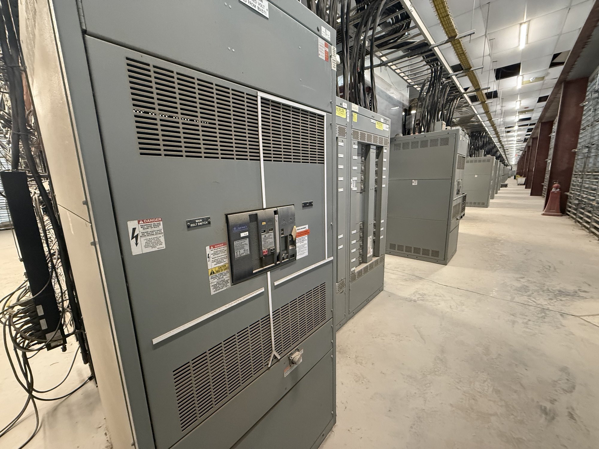
Treat support obsolescence as a planning trigger
A component can become difficult to support well before an entire switchboard is ready for replacement. Ask whether the original manufacturer still supports the installed equipment, whether compatible breakers and accessories remain available, and whether maintenance staff can obtain reliable technical documentation. Record discontinued parts, repair limitations, and any temporary workarounds. These facts show where a single failure could become a prolonged outage rather than a routine maintenance task.
Obsolescence does not automatically require immediate replacement. Compare the cost and feasibility of maintaining the existing assembly with a planned changeout, and consider how long the facility can tolerate constrained support. Identify critical loads, acceptable outage windows, and dependencies such as upstream protection or control circuits. A planned purchase of new switchgear can provide a defined configuration and procurement path, but the replacement scope must reflect the actual installation and engineering review.
Use condition evidence, not age alone
Assess condition through qualified electrical personnel using the facility’s maintenance procedures and appropriate inspection practices. Useful records may include inspection findings, test results, operating history, fault or trip events, environmental exposure, and known modifications. Look for recurring issues such as overheating evidence, corrosion, damaged insulation, difficult breaker operation, or unreliable mechanisms. These observations should be evaluated in context; appearance alone does not establish the condition of internal components.
Document what is known and what remains uncertain. Note which sections were inspected, when observations were made, what testing was performed, and any restrictions on access or operation. If records are incomplete, treat that uncertainty as a planning factor rather than assuming the equipment is either serviceable or failed. Engineering review can determine whether continued operation, further investigation, or replacement planning is appropriate and can define the limits of any interim measures.
Recheck capacity when loads change
New production equipment, building additions, electrification, distributed generation, or revised operating schedules can change the demands on an existing assembly. Gather current and projected load information, including peak demand, major motor loads, anticipated future additions, and any changes to the utility supply. Compare those needs with verified equipment data and the facility’s one-line diagram. Do not select a replacement solely by copying nameplate values from an aging assembly.
The design team should establish required system voltage, continuous current, available fault-current assumptions, protective-device functions, and coordination requirements. Confirm whether the project needs additional feeder spaces, metering, control interfaces, or provisions for future circuits. These questions affect the lineup arrangement and the information required for a quote. Final ratings and configuration depend on engineering analysis and review by the applicable authorities; they should not be inferred from a general description of the facility.
Connect replacement timing to risk and outage planning
Risk exposure includes more than the likelihood of a component failure. Consider the consequence of losing each served load, the availability of alternate feeds, the time needed to obtain unsupported parts, and the operational impact of a prolonged outage. Record which loads are critical, whether temporary power is feasible, and what work must occur during an outage. This helps facilities teams prioritize replacement scope and lets procurement compare a planned project with the disruption of an unplanned event.
Map the path from design approval through equipment delivery, site preparation, installation, testing, and return to service. Identify dependencies such as utility coordination, shutdown approvals, access routes, lifting limits, and removal of existing equipment. Installation, connection, testing, and energization require appropriately qualified personnel and applicable engineering and authority review. A delivery date alone does not establish that a project is ready for changeout.
Define a buildable purchasing scope
For a manufacturer quote, share the one-line diagram, existing equipment nameplates, system and fault-current information, required ratings, feeder schedule, protective-device requirements, and preferred lineup dimensions where known. Include photographs or drawings of room access, cable entry, bus connections, and adjacent equipment, while identifying details that still need field verification. State the requested switchboard standard and scope clearly: UL 891 applies to switchboard assemblies, not as a blanket listing for medium- or high-voltage switchgear.
Also provide the target outage period, required delivery location in Georgia, receiving constraints, unloading arrangements, and any project milestones that affect shipment. Explain whether drawings, interface details, or coordination information are needed for approval before production. American-made components, custom-built configurations, and nationwide shipping may be considered in developing the order, but exact scope, availability, and schedule are confirmed for each project. The project team should verify all dimensions and interfaces before releasing equipment for manufacture.
Turn findings into a decision and handoff
Create a short decision record that separates immediate concerns from longer-range needs. Summarize support gaps, condition evidence, load changes, outage consequences, unresolved data, and the engineering actions required before final selection. Assign owners for field verification, design decisions, procurement approval, site readiness, and installation planning. This gives managers a defensible basis to fund a project without treating an estimated equipment life as a firm replacement deadline.
Start by collecting the current one-line diagram, equipment data, maintenance history, and projected load changes, then identify the most consequential support or condition gaps. Share those materials along with Georgia delivery and outage constraints when requesting a quote for new equipment. Resolve missing ratings and interfaces with the responsible engineer before committing to a configuration, and carry the approved scope through drawing review, shipment planning, and qualified installation.