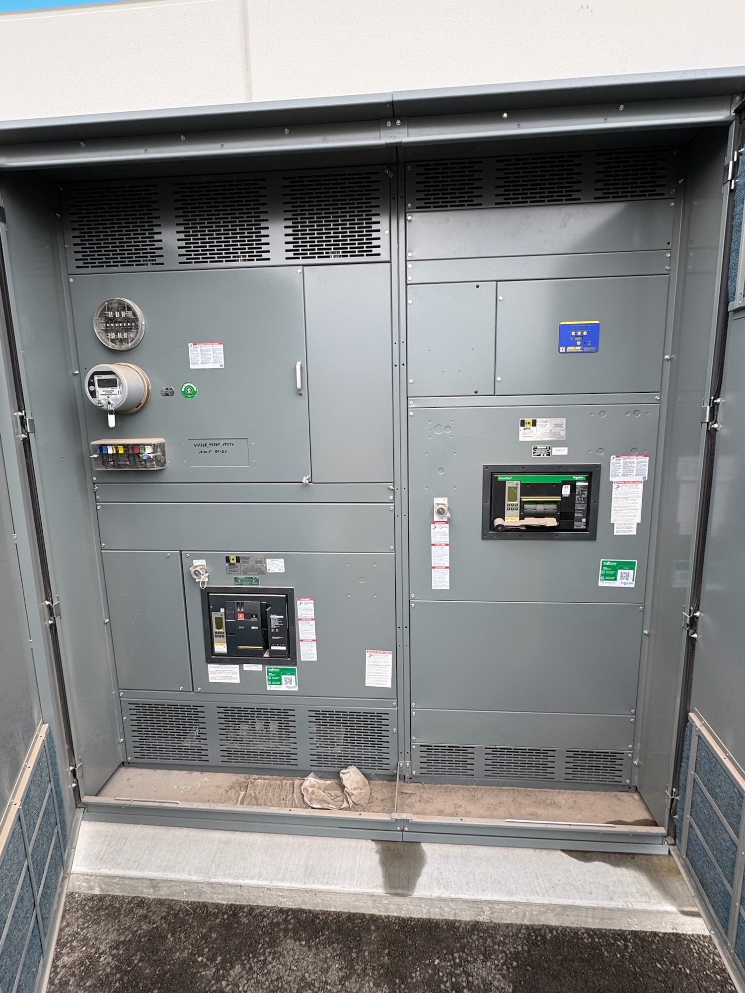
1. Set the commissioning basis
Start with the approved one-line diagram, equipment schedules, coordination and arc-flash studies where applicable, control schematics, sequence of operations, and project specifications. Confirm that the documents identify the equipment lineup, source and load connections, protective devices, metering, interlocks, grounding provisions, and intended operating modes. Record document revisions and resolve conflicting information before field testing begins.
Agree on scope and acceptance criteria with the engineer of record, commissioning authority, contractor, owner and equipment supplier. Identify which checks are visual, mechanical, electrical or functional; who performs and witnesses each; and what test methods and instruments are required. Define hold points, deficiency severity, retest rules and approval authority. Requirements depend on the design, contract documents, manufacturer instructions and applicable standards.
2. Confirm equipment and records
On receipt, compare nameplates, lineup identification, section arrangement, device types and ratings against approved submittals. Check shipping documentation and record visible damage, missing parts or disturbed indicators before installation proceeds. Verify that drawings, wiring diagrams, operation instructions and test documentation match the delivered configuration. Do not assume a familiar model or appearance proves that internal options and connections match the project.
Resolve procurement questions before release for manufacture: what is the system voltage and frequency, available fault current, bus arrangement, incoming and outgoing connection method, enclosure and environment, metering, protective devices, control power and required communications? Identify future provisions, spare spaces and special access or maintenance constraints. For a new UL 891 switchboard assembly, establish the specified scope and documentation; UL 891 applies to switchboards and does not establish a listing for medium- or high-voltage switchgear.
3. Inspect installation conditions
Before electrical tests, confirm the foundation or mounting surface, anchorage, lineup alignment, section joining, required working clearances and access for operation and maintenance against approved drawings and instructions. Inspect for moisture, dust, construction debris, corrosion, shipping braces left in place, and damage to insulation or barriers. Confirm ventilation and environmental conditions are suitable for the specified equipment, and that doors, covers and operating mechanisms move as intended.
Trace field power, grounding and control conductors against the drawings. Check conductor identification, termination preparation, lug compatibility, phase arrangement, torque records where required, and grounding and bonding continuity using the project’s approved methods. Verify that cable bending, support and termination space do not impose undue strain. Keep equipment de-energized and secured under the site’s electrical safety and lockout procedures; only qualified personnel should perform inspections or tests.
4. Complete electrical and functional tests
Select tests from the manufacturer’s instructions, project specifications and applicable standards for the equipment type and condition. The plan may include insulation resistance, contact resistance, circuit-breaker operation and timing, protective-device secondary injection, control-circuit checks, and verification of instrument transformer ratios or polarity. Test voltages, connection points and acceptance values must be appropriate to the equipment; document instrument identification, calibration status, ambient conditions, results and any limits or exclusions.
Check control power, indication, alarms, metering, trip circuits, interlocks and communications against approved schematics and operating sequences. Confirm that each device operates only under intended conditions and that protective settings match the approved coordination study before functional testing. Do not change settings or bypass an interlock to make a test pass without documented engineering authorization. Correct discrepancies, record changes and repeat affected tests before proceeding.
5. Authorize controlled energization
Treat energization as a planned hold point, not the next step after installation. Review open deficiencies, approved test results, protective-device settings, temporary grounds and test leads, covers and barriers, source readiness, load status, switching instructions, communications and emergency actions. Confirm that required permits and approvals are in place and that personnel understand boundaries, responsibilities and the switching sequence. The owner’s authorized operating representative should approve release under the project’s procedures.
Energize in the documented sequence, using qualified personnel and the site’s electrical safety program. Observe indications, alarms, sound, odor and other signs of abnormal operation from appropriate locations; stop and follow the approved response plan if conditions are unexpected. Record switching steps, readings, time, personnel and exceptions. Do not apply power to resolve an unresolved discrepancy or substitute field judgment for engineering review.
6. Close out and prepare the handoff
Deliver a commissioning record that ties each check to the equipment identifier and document revision. Include inspection forms, test results, calibrated instrument details, setting files, approved deviations, deficiency resolutions, retests, energization records and updated as-built drawings. Provide operating instructions, maintenance information and training appropriate to the owner’s responsibilities. Clearly list any remaining restrictions, deferred tests or monitoring needs, with an assigned owner and completion path.
For a Georgia project, share the site location, delivery access and unloading constraints, required arrival window, equipment type, lineup dimensions, electrical and control requirements, specified tests, document submittals and target commissioning sequence when requesting a new-equipment quote. Confirm configuration, availability, shipping plan and schedule for the specific order; coordinate delivery with a prepared, protected installation area. Before handoff, assign an owner to verify that every open item is closed or formally accepted.