Start with the equipment record
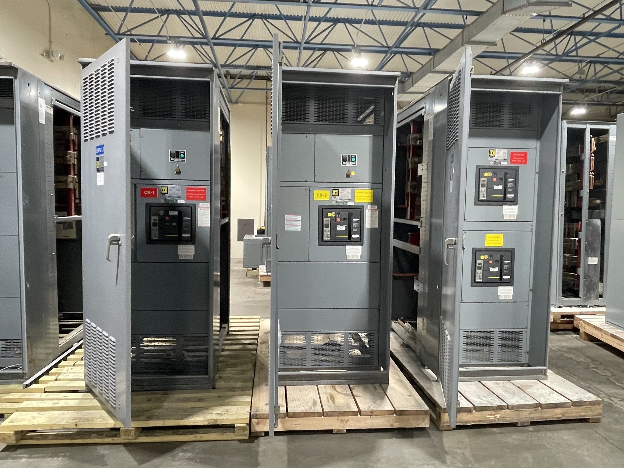
Assessment begins by identifying the assembly and locating the busbar within it. Share the switchgear or switchboard manufacturer, model, serial number, section and compartment, nameplate information, and available one-line diagrams or shop drawings. Record the conductor’s phase or neutral designation, position, and function. These details help specialists distinguish a main bus from a vertical distribution bus or a connection to a breaker, transformer, or other device.
Photographs can clarify the condition, but they do not establish dimensions or electrical ratings. Provide clear views of the affected area and adjacent supports, joints, insulation, barriers, and enclosure. Include overall cabinet views and close-ups with identifying labels visible where possible. Any inspection that requires access to energized equipment must be handled by qualified personnel under the facility’s established electrical safety procedures.
Document the damage and its extent
Describe what was observed: discoloration, pitting, melting, deformation, cracking, loose or damaged joints, damaged plating, or evidence of tracking across insulation. Note whether the condition is localized or appears at multiple connections, and whether nearby insulators, barriers, hardware, cable terminations, or breaker stabs also show damage. A specialist will consider the full current path, because replacing a visibly damaged segment without assessing adjacent components may leave relevant damage unaddressed.
Share when the condition was found and any known operating events, such as a fault, overload, abnormal heating, water intrusion, contamination, vibration, or recent maintenance. Include inspection findings, test reports, and protective-device records if available. Do not treat color or appearance alone as a definitive diagnosis. The assessment should distinguish observed facts from suspected causes and identify what additional inspection or engineering review is needed before repair scope is set.
Establish cause before selecting a repair
Bus damage can result from different mechanisms that require different corrective actions. A high-resistance joint may involve inadequate contact, damaged surfaces, loose hardware, or improper assembly. Fault-related forces can deform conductors or supports, while contamination and moisture can affect insulation and clearances. Specialists compare the damage pattern with the equipment configuration and reported event history to determine whether the likely issue is confined to one connection or may involve a broader section.
Ask what evidence supports the proposed cause and what remains uncertain. The review may identify a need to inspect joint surfaces, verify support condition, check related protective devices, or examine adjacent compartments. Root-cause findings influence whether a local conductor repair, a replacement bus assembly, or a larger equipment modification deserves evaluation. The repair decision should account for the original damage and the conditions that could cause it to recur.
Verify manufacturer and design requirements
A replacement conductor must fit the assembly’s electrical and mechanical design, not merely match a visible length. Relevant information can include conductor material, width and thickness, plating, joint geometry, hole pattern, phase spacing, support locations, insulation system, and connection hardware. The specialist also needs the equipment’s applicable voltage, current, and short-circuit information when available. Do not assume these details from appearance or substitute parts based only on nominal dimensions.
Manufacturer drawings, bills of material, service instructions, and written guidance help establish the acceptable repair method. For older or modified equipment, records may be incomplete; the assessment should identify what must be verified by measurement, engineering review, or manufacturer consultation. Any proposed change to bus configuration, supports, insulation, or connections requires appropriate engineering evaluation and review by the authority having jurisdiction where applicable. UL 891 applies to switchboard assemblies and should not be treated as a blanket listing for other switchgear types.
Choose the scope and prepare the handoff
The assessment should give procurement and project teams a clear basis for comparing repair options. Ask whether the scope covers only the damaged bus, associated joints and supports, or additional components identified during inspection. Confirm the required drawings, material specifications, inspection records, and any testing or acceptance criteria that must be defined by the responsible engineering team. Clarify which party will approve the design, perform field work, and document the completed repair.
For a quote, share equipment identification, drawings and nameplate data, damage photographs, known event history, site location in Georgia, access constraints, and the decision or outage milestone the project must support. State whether the assembly is a switchboard or another switchgear type, and identify any manufacturer requirements already obtained. Georgia delivery can be coordinated with the project’s receiving site and schedule; exact scope, availability, and timeline are confirmed for each order. Before requesting pricing, assemble these records and ask for a written assessment scope that separates verified facts, open questions, and required approvals.