Start with the surge path
Surges can enter through utility conductors, arise from switching events, or couple into wiring from nearby lightning activity. Protection planning should map those paths rather than treat the service entrance as the only point of concern. Identify sensitive loads, long feeder runs, exposed circuits and equipment whose interruption would affect operations. This establishes where protection deserves review and what the project is trying to preserve.
A layered arrangement commonly places a service-level device near the source, with additional protection closer to sensitive or critical loads where the system design warrants it. Layers are not automatically beneficial simply because more devices are installed. Their protective levels, current paths and operating characteristics must be considered together, and the electrical engineer should determine whether the proposed arrangement suits the system and applicable project requirements.
Match ratings to system conditions
Review the nominal system voltage, phase and grounding arrangement before selecting a device. Confirm the device's maximum continuous operating voltage and its connection mode against the actual system, including whether it connects line-to-neutral, line-to-ground, line-to-line or through another specified arrangement. A mismatch can affect performance or expose a device to conditions outside its intended application.
Compare surge current ratings and voltage protection information using the manufacturer's definitions and test basis, not a single number in isolation. Ask how the device is intended to perform at the available fault current and what overcurrent protection or disconnecting means it requires. The engineer must verify that the proposed equipment and protective arrangement are suitable for the installation; ratings should not be inferred from a switchboard nameplate or a general product category.
Coordinate locations and connections
Physical placement affects the voltage that reaches protected equipment during a surge. Connection conductors should follow the device instructions, with attention to conductor length, routing, bend geometry and the specified connection method. Long or indirect leads can add impedance and reduce the benefit of placing a device near the service. Confirm the enclosure location and cable path on drawings before the assembly and field wiring are finalized.
Where service-level and downstream devices are proposed, review their coordination using manufacturer guidance and the system's actual configuration. Different device types or brands should not be presumed coordinated from their labels alone. Check whether the instructions require separation, a particular upstream device, or other installation conditions. Field routing, available mounting space and the switchboard layout may constrain the intended arrangement and should be resolved during design review.
Read instructions as design inputs
Installation instructions define more than mounting details. Review conductor material and size, terminal torque, required overcurrent protection, grounding connections, environmental limits, status indication and replacement criteria. Confirm whether the specified device is suitable for the intended enclosure and location, and whether remote alarm contacts or monitoring connections are needed. These details influence drawings, procurement and commissioning plans.
Clarify how the device will be inspected and what an indication of end-of-life means for operations. A status window or alarm contact can support maintenance, but the facility needs a defined response and access plan. Surge protection does not eliminate the need to assess grounding and bonding, nor does it protect every connected circuit by default. Include control, communications and other conductors in the review where the project requires protection for them.
Set the switchboard scope clearly
For a new switchboard, provide the one-line diagram, system voltage and grounding details, service and feeder arrangement, available fault-current information, and the requested device location. Identify the loads or downstream panels that drive the protection strategy, along with enclosure constraints, monitoring needs and any project specifications. These inputs let the manufacturer review the requested configuration and identify questions before the order is finalized.
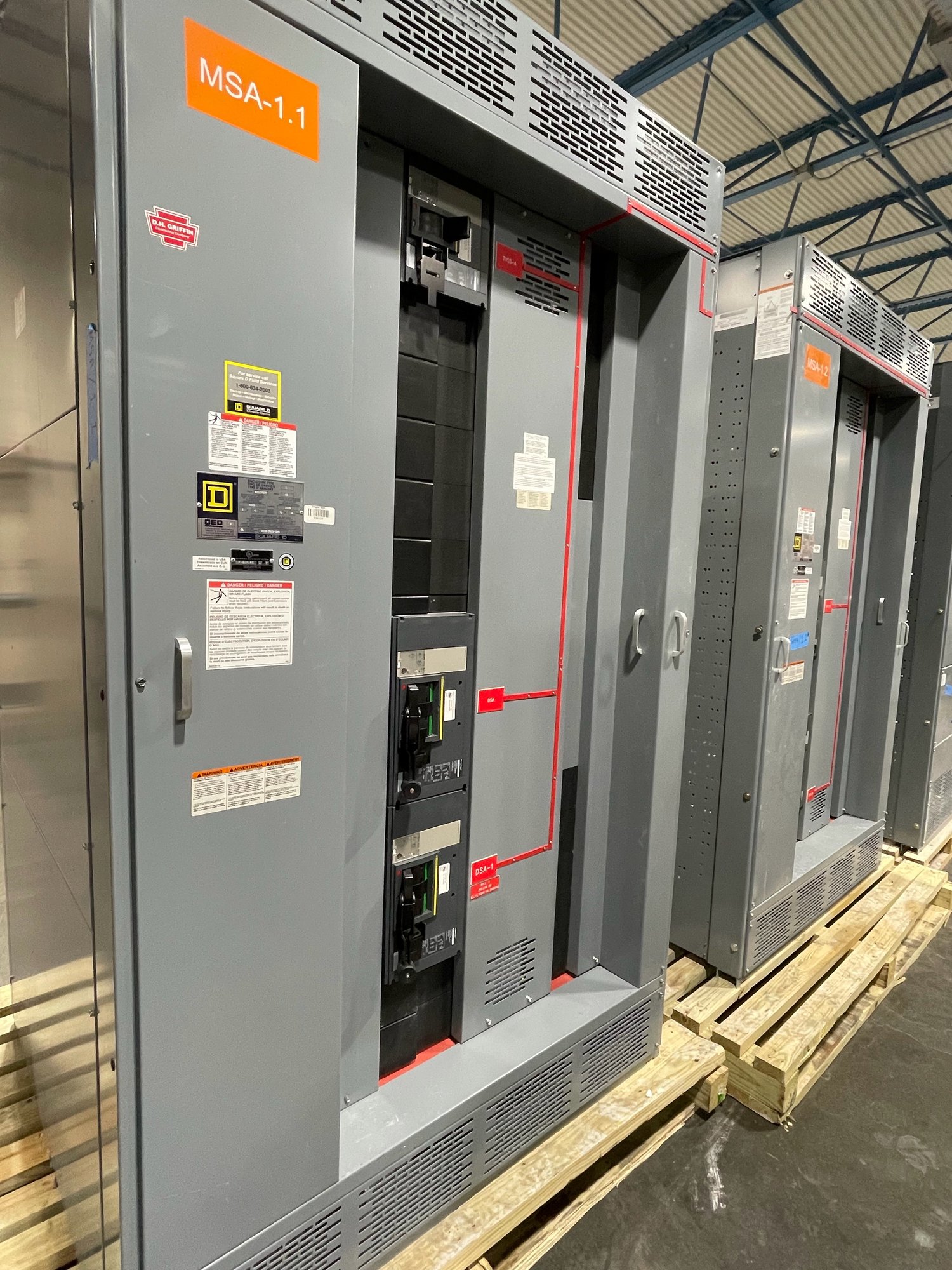
A UL 891 switchboard assembly is built to the applicable switchboard standard; that designation does not, by itself, establish the ratings or suitability of every surge protection device or prove that a complete protection scheme is coordinated. The design team must review device documentation, system calculations and project requirements. Confirm the exact scope, component availability and production schedule for each order rather than assuming every requested option is standard or immediately available.
Plan handoff through Georgia delivery
Before release, align the approved one-line and layout with the device schedule, connection details, installation instructions and responsibility for field wiring. Resolve who supplies any external disconnects or conductors, who verifies settings or torque, and what documentation the commissioning team needs. Changes to voltage, grounding, feeder arrangement or device selection after approval can affect the configuration, so route revisions through the engineering and procurement teams.
For a Georgia project, share the delivery site, required receiving window and site access constraints when requesting a quote. Nationwide shipping can support delivery to the project location, but the order-specific shipping plan and timing must be confirmed. The next practical step is to send the one-line, service data, preferred protection locations and applicable specifications for review, then reconcile device instructions and final layout before authorizing the new switchboard build.