Two sources, different paths
A lightning surge can enter an electrical system through a direct strike, a nearby strike coupled onto conductors, or a utility line carrying an induced transient. Its steep wavefront and high energy can stress insulation, bus, cable, and connected equipment. Exposure depends on the service arrangement, overhead or underground supply, grounding and bonding, and the facility’s location and site features.
Switching transients arise when loads or circuits change state. Opening or closing breakers, energizing transformers, switching capacitor banks, and interrupting inductive loads can produce transient overvoltages. Their magnitude, duration, and repetition depend on the circuit and switching conditions. A design that addresses lightning exposure does not automatically address every internally generated transient.
Map exposure before selecting devices
Start by tracing likely surge paths from the utility service through the main switchboard and downstream distribution. Identify overhead service conductors, transformers, long feeders, capacitor banks, motor loads, and sensitive electronic equipment. Ask the utility or electrical engineer about service characteristics and known switching events; site records and disturbance logs can help distinguish recurring internal events from external exposure.
Protection is a coordinated system, not simply a device rating chosen in isolation. The engineer should evaluate the installation’s grounding and bonding, available fault current, system voltage, conductor routing, and the equipment’s withstand requirements. A surge protective device (SPD) may limit transient voltage at its connection point, but its performance depends on device characteristics, placement, lead length, and coordination with other protection.
Specify protection by location and duty
For a switchboard, clarify whether the design calls for an SPD at the service entrance, distribution equipment, or both. Discuss the intended protection mode, voltage protection level, nominal discharge current, short-circuit current rating, and disconnect or overcurrent protection requirements with the engineer. Selection must match the system configuration, including grounded or ungrounded arrangements and any neutral connection, rather than relying on a generic catalog description.
Lightning-related exposure may call for service-level protection and coordination with upstream utility and site measures. Switching transients may require attention closer to the equipment producing the event or the load needing protection. Surge devices do not replace circuit breakers, grounding, insulation coordination, or controls for repeated switching events. Confirm the applicable standards, installation rules, and device compatibility with the project engineer and authority having jurisdiction.
Coordinate the switchboard interface
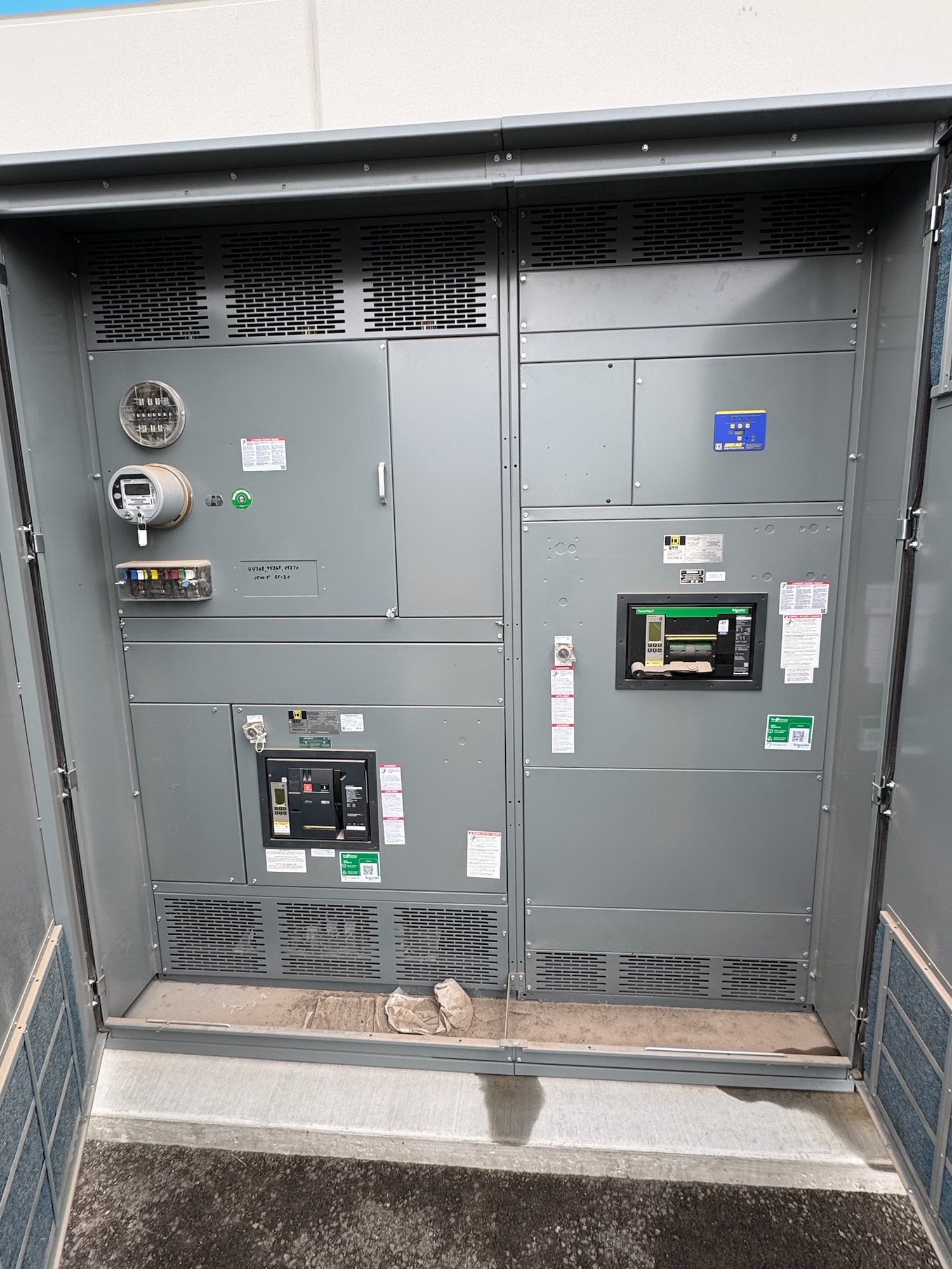
When a new switchboard is part of the project, provide the manufacturer with the one-line diagram, system voltage and configuration, service and feeder details, available fault current, and the engineer’s specified SPD requirements. Identify whether the protective device is to be integrated into the assembly or supplied separately, and show its intended location, connection point, disconnecting means, and any monitoring or alarm contacts required.
Physical arrangement affects the design. An integrated SPD needs suitable space, bus or conductor connections, overcurrent coordination, and access for inspection and replacement by qualified personnel. Long connecting conductors can increase the voltage seen by protected equipment, so the engineer should review the layout and connection path. Confirm enclosure, environmental, and terminal requirements for the actual installation rather than assuming a standard configuration will fit.
Resolve scope and procurement details
For a quote, share the project location in Georgia, requested delivery window, quantity, equipment type, one-line diagram, voltage and ampere ratings, fault-current information, and the exact surge-protection specification or design criteria. Include the identified transient sources, existing protection, and any required alarm or monitoring features. If the SPD selection is not finalized, state who will provide the engineering decision and when it is expected.
Confirm what the switchboard scope includes: device, mounting, connections, protection components, documentation, and any specified assembly requirements. UL 891 applies to switchboard assemblies, not as a blanket certification for every surge device or for medium- and high-voltage switchgear. We build new equipment in the United States using American-made components, with custom configurations, short lead times, and nationwide shipping; exact scope, availability, and schedule are confirmed for each order.
Carry decisions through delivery
Before release, reconcile the approved one-line diagram, device data, switchboard drawings, and project specifications. Resolve any differences in system grounding, SPD ratings, connection details, or responsibility for upstream and downstream protection. For Georgia delivery, confirm the jobsite, receiving contact, access and unloading constraints, required delivery sequence, and date coordination so equipment arrives in step with installation planning.
Gather the transient history and design criteria now, then send the one-line, service data, fault-current value, and requested protection scope with the quote inquiry. Ask the project engineer to approve device selection and coordination, and confirm the manufacturer’s drawing and delivery schedule before release. That handoff reduces ambiguity between surge protection design, switchboard configuration, and field installation.