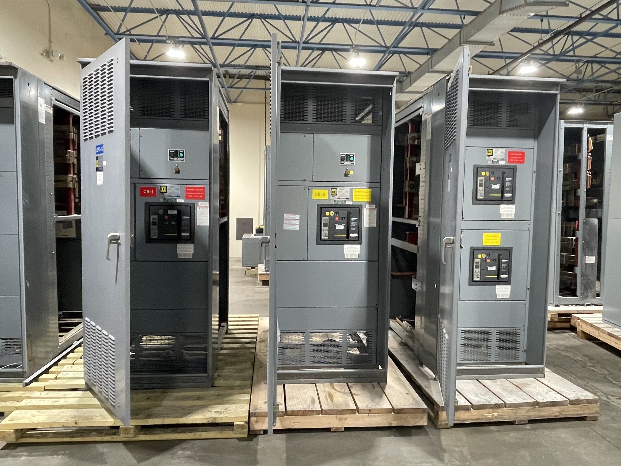
Start with load and generator data
A generator’s nameplate rating alone does not establish the required distribution arrangement. Share the generator voltage, phase, frequency, rated output, available fault-current information and any limits on output or neutral configuration. Identify whether the source is a single unit, multiple paralleled generators, or a generator intended to serve a defined portion of the facility. These details influence switchboard bus, main-device and connection requirements.
Provide a load schedule that distinguishes continuous loads, motor starting or other transient demand, and loads that will be shed or sequenced. Note expected growth, planned operating modes and any loads that must remain available during transfer. The generator, conductors, overcurrent devices and switchboard must be evaluated together by the project engineer; do not size the assembly from a general building load figure without confirming the design basis.
Define the transfer interface
Identify the transfer equipment type and where it sits relative to the generator, normal source and distribution assembly. The design may use a separate automatic transfer switch, multiple transfer switches serving different load groups, or another engineered arrangement. Clarify whether the switchboard receives the generator output directly, distributes power downstream of transfer equipment, or includes a designated interface for transfer equipment furnished elsewhere.
For each transfer point, provide the source and load voltages, pole configuration, ampere requirements, bypass or isolation needs if specified, and intended control and status connections. Confirm which party furnishes the transfer equipment and which party provides interconnecting conductors, terminals and controls. These scope boundaries prevent gaps between switchboard drawings, transfer equipment submittals and field installation responsibilities.
Coordinate protective devices
Generator fault current can differ substantially from utility-source fault current and may decay over time. Provide the available fault-current data and generator manufacturer’s applicable information so the engineer can evaluate interrupting ratings, device selection and coordination under the intended source conditions. Identify upstream and downstream protective devices, their settings where established, and whether selective coordination or particular operating sequences are required by the project.
Ask the engineer to review protection for both normal and standby modes, including how transfer changes the source feeding each circuit. Settings and coordination depend on the complete system, not just the switchboard. The assembly’s configuration and device options can be developed to the approved design, but final protection studies, settings, and acceptance remain subject to project engineering and the authority having jurisdiction.
Choose connection and neutral details
Specify how generator conductors will enter and terminate at the distribution equipment: top or bottom entry, cable or bus connection, lug requirements, conductor material and size, and the available bending and routing space. Include the generator location, approximate conductor route and any transition equipment so the design team can check practical installation constraints. Confirm whether the generator is separately derived and how neutral switching and grounding are addressed in the engineered system.
Also identify enclosure location and environmental conditions, access and working-space constraints, and whether the assembly must align with existing distribution equipment. A new switchboard may be configured for the required arrangement, but dimensions, ratings, clearances and termination details must be verified against approved drawings and site conditions. Avoid assuming that a familiar connection layout will fit a different generator room or electrical space.
Prepare a useful quote package
For a quote, share the one-line diagram, load schedule, generator data, transfer-equipment scope, fault-current information, device and coordination requirements, connection preferences, and project schedule. Include the required assembly scope, control interfaces, drawing and submittal needs, and any known site limitations. Mark unresolved items clearly rather than treating preliminary values as final; the quote can then identify what remains to be confirmed before release for production.
American-made components, custom-built configurations and UL 891 switchboard assemblies are available as project requirements allow. UL 891 applies to switchboards; it does not establish a blanket listing for medium- or high-voltage switchgear. Exact scope, component availability, assembly details and timeline are confirmed for each order against the final specification.
Plan delivery and field handoff
For Georgia projects, coordinate the requested delivery location, receiving hours, unloading arrangements, access route and required delivery sequence with the procurement and site teams. Nationwide shipping supports projects across the state, but the project schedule should allow for confirmation of the order’s scope and timing rather than relying on an assumed lead time. Tell the supplier when the switchboard must be available for setting, conductor termination, inspection or planned generator commissioning.
Before releasing the order, reconcile the approved one-line, equipment schedule, transfer interface, protection requirements and connection details across the project team. Assign responsibility for field conductors, controls, grounding, settings and commissioning, and route unresolved technical questions to the responsible engineer. This handoff gives the manufacturer a defined basis for building the assembly and helps the contractor plan a coordinated installation without making assumptions about the site design.