Define the service boundary
Service entrance equipment receives power at the customer’s service point and provides the means to distribute and protect it downstream. The arrangement may include service disconnects, bus, overcurrent devices, metering provisions, and feeder sections, but the exact functions depend on the service design and utility rules. Establish which equipment belongs to the utility and which is part of the customer installation before defining the assembly.
Start with the service voltage and phase, number of service conductors or sets, available fault-current information, service-disconnect arrangement, and the loads the switchboard must supply. Clarify whether the equipment is indoors or outdoors, the installation environment, cable entry direction, and space available for access and termination. These are design inputs, not details to assume from a building address or a prior project.
Coordinate utility and authority requirements
The serving utility may specify acceptable service configurations, metering arrangements, CT compartments, sealing provisions, service conductors, and access clearances. Georgia projects can involve different utility requirements, so identify the actual provider and obtain its current service standards and project-specific direction. Confirm early whether utility review is required before equipment release, and who will submit drawings and resolve comments.
The electrical engineer must coordinate the service design with applicable codes and the authority having jurisdiction. Review requirements can affect disconnect grouping, overcurrent protection, grounding and bonding provisions, meter location, and equipment placement. Utility acceptance, equipment construction, and approval of the installed electrical system are distinct matters. Do not treat a manufacturer’s drawing review or an equipment standard as a substitute for project engineering or authority approval.
Specify the assembly for the site
Provide the required bus rating, main-device type and rating, number and ratings of outgoing devices, and any future spaces or provisions. Identify the system grounding arrangement, neutral requirements, and whether the project needs a main section, distribution sections, or a particular lineup. Share available fault current and the engineer’s required short-circuit and protective-device information so the design can be evaluated for the actual application.
Physical constraints can determine whether a proposed lineup works. Give the room or pad dimensions, working-space plan, access route, door and corridor limits, mounting method, environmental conditions, and preferred cable entry and exit. Include conductor material and termination needs when known. If the project has unusual access, exposure, or maintenance constraints, describe them during quoting; final construction details depend on confirmed engineering and equipment scope.
Make metering and protection explicit
Metering scope should be clear before drawings are developed. State whether the utility or customer provides the meter and instrument transformers, where they must be located, and whether provisions for remote monitoring or customer metering are required. Confirm instrument-transformer ratios and compartment details with the utility and engineer rather than selecting them from assumptions. Also identify any required control power, indication, communications, or interlocking interfaces.
Protection decisions belong to the project’s electrical design. Share the specified device types, trip functions, settings responsibilities, coordination study requirements, and any selective-coordination or arc-energy objectives. The manufacturer needs approved device and arrangement information to build the intended configuration, but cannot infer study results or guarantee coordination from a one-line diagram alone. Keep setting, testing, and commissioning responsibilities clear in the project documents.
Prepare a complete quote and submittal package
For a useful quote, provide the one-line diagram, service data, equipment schedule, utility requirements, fault-current information, room or site layout, and requested delivery location in Georgia. Include the desired lineup dimensions, main and branch device details, metering scope, cable termination information, environmental conditions, and required accessories. Flag unresolved items so the proposal can identify assumptions rather than presenting them as confirmed requirements.
A typical submittal package can include a proposed one-line representation, elevation and dimensions, device schedule, and relevant equipment data, with content determined by the order scope. Review drawings against the utility’s requirements, engineering documents, and site conditions before approval for production. Resolve deviations in writing and identify who returns consolidated comments. This review stage helps prevent late changes to compartments, cable access, or overall lineup arrangement.
Plan release, delivery, and handoff
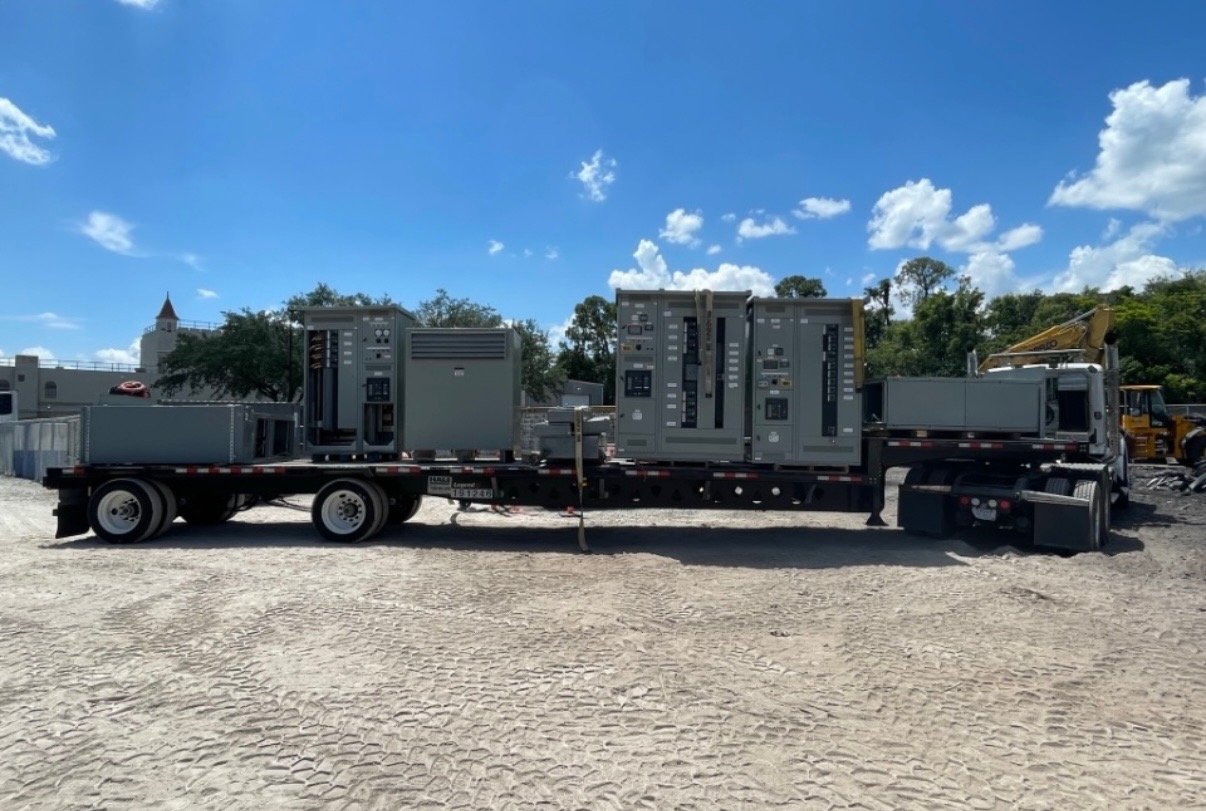
New service entrance switchgear is built to the confirmed configuration; availability and schedule are established for each order. Discuss required ship date, delivery access, unloading responsibility, receiving hours, storage conditions, and any site restrictions when requesting a quote. Georgia delivery planning should account for the route to the installation point, not just the destination address, especially where equipment must pass through limited doors or reach an elevated or restricted area.
Before release, send the current approved drawings, utility comments, engineer’s requirements, and final site information together. At handoff, coordinate shipment with the installing contractor and receiving team, and ensure qualified personnel handle installation, inspection, testing, and energization under the project plan. Begin by gathering the utility’s service criteria, the engineer’s one-line and fault data, and the site dimensions; these inputs let the manufacturer define a practical quote and submittal path for the project.