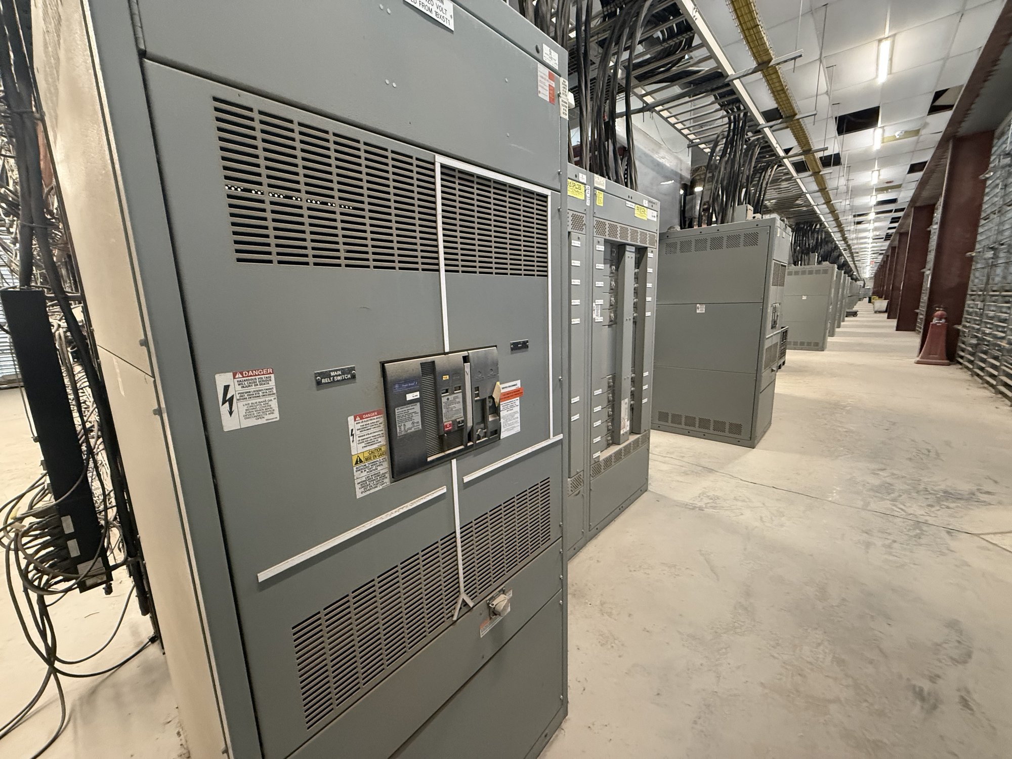
Define the equipment and its role
“Pad-mounted switchgear” can describe different arrangements, so begin by defining what the assembly must do. Identify the system voltage, phase, frequency, source and load connections, required switching functions, and whether the scope includes a transformer or separate distribution equipment. A one-line diagram and equipment schedule help distinguish a loop-feed arrangement from a radial application and clarify which devices must isolate, sectionalize, or protect each circuit.
Record the required continuous current and short-circuit duty at the installation point, along with grounding method and operating sequence. Specify the number and type of incoming and outgoing ways, cable termination requirements, metering provisions, control power, and any remote monitoring or interlocking needs. These are engineering inputs, not assumptions to infer from a general product label; the design team and serving utility must establish applicable values.
Coordinate the utility interface early
The utility interface can determine the enclosure arrangement, cable entry locations, switching provisions, metering, and ownership boundaries. Ask the utility for its current service requirements, approved connection approach, protection expectations, access rules, and review process. Confirm whether utility-owned and customer-owned conductors terminate in separate compartments, who supplies terminations or metering components, and what information the utility needs before it will review the design.
Show the proposed equipment on the project one-line and site plan, and identify the serving utility, point of delivery, source configuration, and anticipated load. Clarify responsibilities for equipment, cable, grounding, testing, and energization in the project documents. Utility acceptance and final system design remain subject to the utility’s requirements and review; a manufacturer quotation cannot substitute for that approval.
Fit the enclosure to the site
A pad-mounted unit needs more than a footprint. Check the pad dimensions and elevation, finished grade, drainage, surface slope, and the space needed to open doors or operate handles. Maintain the working and access clearances required by the equipment design, project documents, applicable rules, and authority having jurisdiction. Account for walls, fences, landscaping, parked vehicles, adjacent equipment, and future construction that could obstruct operation or maintenance.
Confirm cable routes, bend space, conduit locations, and underground conflicts before the pad is poured. Consider flood exposure, standing water, soil and foundation conditions, corrosion exposure, and the possibility of vehicle impact. Where barriers are proposed, make sure they do not block doors, lifting points, or service access. The project engineer and relevant authorities should review the site layout and determine the required clearances and protective measures.
Plan for operating access and maintenance
A unit that fits on paper may still be difficult to deliver or operate. Map the route from the delivery point to the pad, including gate openings, turning radius, overhead obstructions, pavement capacity, and any restrictions on truck or lifting equipment access. Confirm the equipment’s shipping dimensions and weight for the selected configuration, then coordinate unloading and placement with the contractor responsible for the site.
Plan who will operate and maintain the equipment, how authorized personnel will approach it, and whether doors can open fully without conflict. Specify labeling, keying, interlocks, provisions for grounding, and accessories needed for the intended operating procedure. Operating instructions and maintenance requirements should be reviewed by qualified personnel before installation and service; do not treat an enclosure arrangement as a substitute for a site-specific safety review.
Resolve configuration and procurement details
For a manufacturer quotation, share the one-line diagram, load and fault information available to the design team, utility requirements, site plan, cable and conduit details, and a clear scope boundary. State whether the request includes a transformer, protection devices, metering provisions, controls, or accessories, and identify any preferred arrangement or constraints. If inputs are not final, mark them as preliminary and list the decisions still pending rather than allowing an assumption to become a purchase requirement.
Review the proposed equipment schedule against the electrical documents before release. Confirm interface points, device functions, termination orientation, enclosure access, finish or environmental requirements, documentation, and any required review submittals. American-made components and custom-built configurations can be considered for the specified scope. Component selection, availability, and production timing are confirmed for each order; they should not be presumed from a general product description.
Coordinate delivery and project handoff
For Georgia projects, connect the delivery plan to the construction sequence. Provide the jobsite address, receiving hours, site contact through the project team, access restrictions, unloading method, target delivery window, and whether the pad and approach will be ready. Nationwide shipping can support Georgia destinations, but the route, freight arrangements, equipment configuration, and schedule must be confirmed for the individual order.
Before equipment release, reconcile approved drawings and utility comments with the purchase scope, pad details, cable entries, and delivery assumptions. At handoff, give the installing contractor the approved equipment documents and coordinate any open questions with the project engineer and utility. To request a quote, send the one-line, site plan, utility criteria, required functions, and delivery constraints together so configuration, interfaces, and schedule can be evaluated as one project.