What the protection detects
A generator operating in parallel with a utility source or another generator normally delivers real power to the connected system. If prime-mover input falls too low while the generator remains electrically connected, the machine can draw real power from the system and run as a motor. Reverse power protection detects this change in direction, typically by monitoring real-power flow through instrument transformers and evaluating it with a protective relay.
The relay’s response depends on the application. It may provide an alarm, trip the generator breaker, or initiate another engineered sequence. The intent is not simply to react to any brief power fluctuation: settings and time delay must account for normal operating transitions while responding to sustained power import that indicates an unwanted condition. The protection scheme should be coordinated with the generator controls and the overall operating sequence.
Why unintended import matters
When a prime mover loses torque or its fuel or energy input is interrupted, a synchronized generator may continue turning by drawing power from the bus. This can impose a motoring load on the engine or turbine and may create operating or equipment concerns. Reverse power protection provides a way to detect that state and separate the affected generator from the system according to the approved control philosophy.
The consequences and appropriate response vary by prime mover, generator design, operating mode and system configuration. A site with utility paralleling has different coordination considerations from an isolated plant with multiple generators. Engineers should establish what condition the relay is meant to detect, what other protections operate, and whether alarm, trip or both are required. The relay function does not replace generator, engine, turbine or system-level protection.
Settings require application data
Reverse power pickup and time delay are application-specific. The generator manufacturer’s motoring limits, expected minimum stable loading, prime-mover characteristics, measurement accuracy and transient behavior can all affect the settings. Engineers should obtain applicable equipment data and study the operating scenarios rather than selecting a threshold from a generic example. Relay settings and trip logic require review by qualified protection professionals.
The design also needs to define how the relay measures power direction and how it behaves during startup, synchronization, load rejection and shutdown. Confirm the voltage and current sensing arrangement, polarity conventions, phase relationships and relay input requirements. Incorrect sensing connections or logic assumptions can impair directional measurement. Coordination with loss-of-field, overcurrent, frequency, voltage and other generator protections should be evaluated as part of the protection study.
Coordinate the breaker and controls
A protection scheme is only useful when its output reaches the intended device and produces the intended action. Specify the generator breaker interface, trip circuit arrangement, auxiliary contacts, alarm outputs, control power and any required interlocks. Identify whether the relay is to trip directly, communicate with a control system, or participate in a broader sequence. The engineer should define reset behavior and how operators will recognize and investigate an operation.
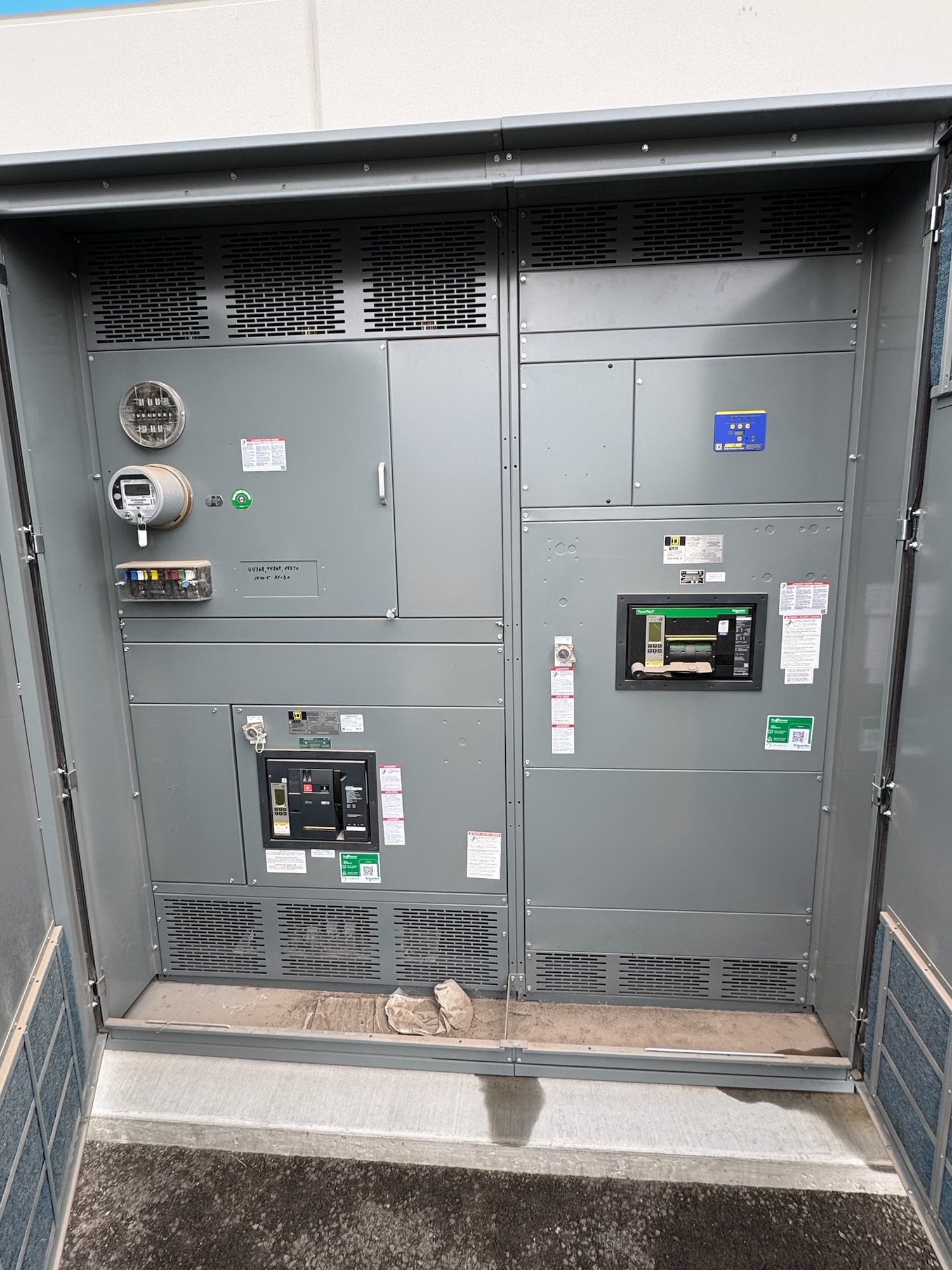
For a new switchboard or switchgear project, the one-line diagram, elementary diagrams, relay requirements and equipment boundaries should agree. Confirm who supplies sensing transformers, protective relays, wiring, generator controls and commissioning settings. The switchgear assembly can be configured to the project’s defined interfaces, but the protection scheme and settings must be established through engineering review. UL 891 applies to switchboard assemblies; it is not a blanket listing for medium- or high-voltage switchgear.
Prepare a useful project specification
For a quotation, share the latest one-line diagram, generator quantity and ratings, system voltage, grounding arrangement, paralleling method and intended operating modes. Include the prime-mover type, generator and control-system documentation, existing relay or breaker information, required alarm and trip actions, and any owner or engineer specifications. Note whether the project is new construction, an expansion or replacement, and identify the equipment boundaries and required interfaces.
Also provide the project location in Georgia, delivery constraints, requested schedule, submittal requirements and any site-specific receiving or access conditions. These details help determine assembly scope, component availability and a realistic order timeline; exact configuration and timing are confirmed for each order. New equipment can be custom-built around defined project requirements, with American-made components where applicable and nationwide shipping arranged for the project.
Close the engineering handoff
Before release for manufacture, reconcile the approved drawings, protection narrative, relay functions, breaker trip logic and responsibility matrix. Resolve open questions about sensing, control power, communications, alarms and field wiring. The engineer of record and relevant equipment specialists should review the design, settings and coordination; installation, testing and energization belong to qualified personnel following approved project procedures.
To move a Georgia generator project forward, send the one-line diagram and protection requirements with the requested equipment scope, delivery destination and schedule constraints. Ask the project team to identify who will provide final relay settings and approve the trip sequence. A clear handoff makes it easier to configure new switchgear around the intended reverse-power response without assuming a setting or operating philosophy that has not been engineered.