Why abnormal phase conditions matter
A phase loss occurs when one phase of a three-phase supply is interrupted. It can result from an upstream fault, a failed connection, a blown fuse, or another open-circuit condition. A motor that continues running on the remaining phases may draw excessive current, overheat, lose torque, or fail to start under load. The consequences depend on motor design, loading, and how long the condition persists.
Phase unbalance means the phase voltages or currents differ rather than one phase being fully absent. Even a modest voltage unbalance can produce a much larger current unbalance in an induction motor, increasing heating and shortening insulation life. Pumps, fans, compressors, conveyors, and process equipment may also experience reduced performance or nuisance interruptions. Protection should reflect the equipment’s operating limits, not assume every deviation has the same impact.
Choose what the protective device measures
A phase-monitoring relay may compare phase-to-phase or phase-to-neutral voltages, depending on the system configuration and device capabilities. Some devices detect phase loss, incorrect phase sequence, undervoltage, overvoltage, and voltage unbalance; others cover only selected conditions. Current-based monitoring can provide a different view of motor loading. The sensing method, monitored location, and system grounding arrangement should be established with the project engineer.
Ask what thresholds and time delays are adjustable, how the device responds during starting, and whether it provides a separate alarm output. A short disturbance may warrant an alarm or delayed trip, while a sustained loss may require prompt disconnection. Settings must suit the motor, load, controls, and coordination study. Do not select a relay solely by nominal voltage or assume a feature is included without confirming the specified device and configuration.
Coordinate sensing with motor protection
Phase monitoring complements, rather than replaces, motor overload and short-circuit protection. Overload devices respond to current and their time-current behavior; a voltage-monitoring relay can identify supply conditions that may not be adequately addressed by overload protection alone. Engineers should review how these functions interact with starters, contactors, circuit breakers, fuses, and any drive or soft starter in the circuit.
Define the intended action for each detected condition: trip the motor, inhibit starting, alarm, or signal a supervisory system. Confirm whether the relay output operates a control circuit directly or interfaces through a control device, and identify reset requirements. For multiple motors, determine whether each feeder needs independent monitoring or whether a common upstream monitor is appropriate. The answer depends on circuit layout, operating priorities, and the consequences of stopping equipment.
Specify the assembly and interfaces
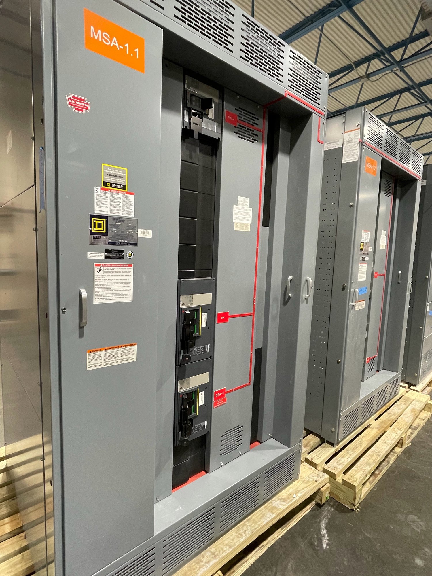
For a new switchboard or switchgear order, provide the one-line diagram, system voltage and frequency, available source arrangement, feeder schedule, motor nameplate data, and control schematics when available. Identify which loads require phase-loss or unbalance protection, their starting methods, and any existing protective devices that must coordinate with the new assembly. Include desired alarm points, remote indications, communications needs, and control-power details.
UL 891 applies to switchboard assemblies; it is not a blanket listing for medium- or high-voltage switchgear. State the equipment type and applicable project requirements clearly so the proposed scope can be reviewed correctly. Device selection, protective settings, assembly design, and installation details require review by qualified engineering personnel and the authority having jurisdiction. Exact configuration and availability are confirmed for each order.
Plan the quote and Georgia delivery
For a useful quotation, share the project location in Georgia, requested equipment type, target ship date, drawings, motor list, and the required protection functions. Flag whether the work is a replacement, expansion, or new installation, and explain any constraints on dimensions, cable entry, access, or integration with existing controls. Identify the party responsible for final settings and commissioning so the handoff is clear.
New assemblies are built to the confirmed project scope using American-made components where specified and available. Shipping can be arranged nationwide, including delivery to Georgia, with routing and timing confirmed for the order. Before release, review the approved drawings, device schedule, control interfaces, and documentation requirements. Provide the motor and system data early so engineering review can resolve how phase conditions are detected and what the equipment should do when they occur.