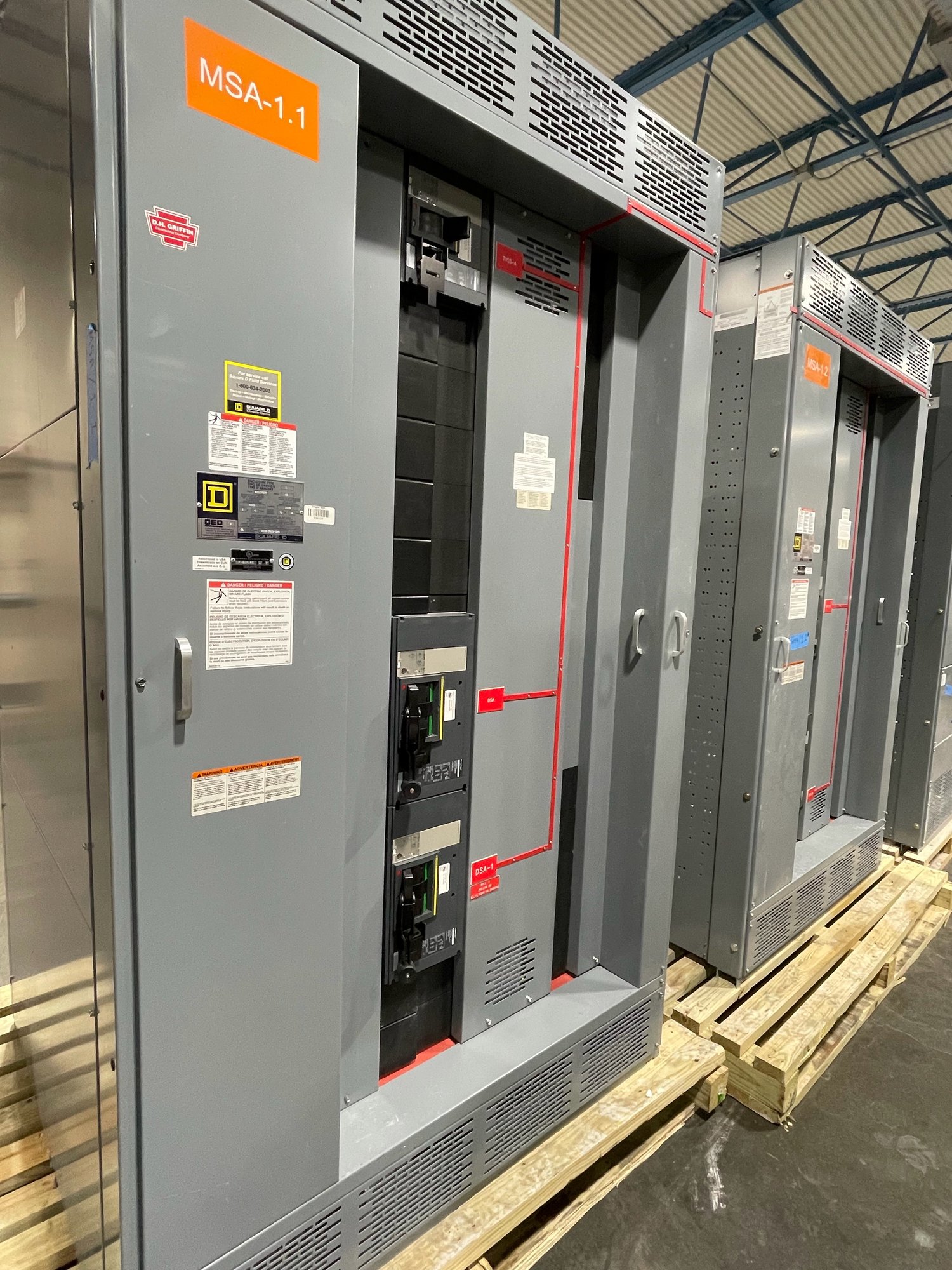
Map the loads and service arrangement
Begin with the one-line diagram and a clear division between landlord and tenant loads. Document the utility service arrangement, service voltage, available fault-current information, service entrance equipment, and loads for lighting, HVAC, signage, refrigeration, pumps and other shared systems. The engineer of record should establish applicable calculations and protection requirements; equipment selection depends on that project-specific design.
For a center with multiple buildings or lease areas, identify where power enters, how it is distributed and which party owns each portion. Show existing equipment that will remain, planned additions and any limits on space or access. These details help define whether a project needs a main switchboard, distribution sections, tenant feeder provisions, or a coordinated combination rather than a generic equipment package.
Make tenant metering workable
Tenant metering affects both electrical layout and lease administration. Decide whether each tenant has a dedicated meter, whether meters are grouped in a common electrical room, and how landlord loads are separated. Confirm meter type and communications expectations with the utility, metering provider, engineer and property team. Meter locations, compartments and wiring provisions must suit the selected arrangement and the project's applicable requirements.
A useful quote package identifies the number of tenant spaces at initial occupancy and any anticipated future divisions, along with each meter's placement and ownership. Include the metering schedule, one-line diagram and any requirements for utility-furnished components. Do not assume every metering arrangement can be accommodated in the same switchboard configuration; available space, service design and equipment scope need review.
Plan feeders for changing tenants
Retail tenants change, and a space may be subdivided, combined or assigned a different use. Flexible feeder planning can make those transitions easier when the design provides defined spare capacity, suitable distribution points and a practical route to each tenant area. The engineer should specify feeder sizes, overcurrent protection and conductor pathways based on calculated loads, distance, installation conditions and the intended tenant mix.
When requesting equipment, distinguish installed feeders and devices from provisions for later work. State which tenant circuits are part of the initial phase, which spaces are future, and whether reserved breaker positions, bus capacity or other provisions are requested. A spare position is not automatically usable capacity: bus, enclosure, thermal and fault-duty limits must be evaluated for the actual design.
Size service capacity with phases in mind
Service capacity should reflect the project's load calculations and operating assumptions, not simply the number of storefronts. Ask the engineer to evaluate known tenant loads, common-area demand, anticipated occupancy, demand factors, motor starting and any planned electric vehicle charging or other significant additions. Utility service availability and fault-current data can constrain the equipment design and should be confirmed before the order is finalized.
Phased construction adds a procurement choice: install equipment for the complete planned development, or define a first-stage arrangement with a documented expansion path. Compare the cost and footprint of initial capacity against future shutdowns, utility coordination and replacement work. Any future expansion assumptions should be explicit in the drawings and reviewed by the responsible engineer; available capacity cannot be inferred from an empty enclosure or unused breaker space.
Coordinate scope, schedule and delivery
For a manufacturer quote, share the current one-line and equipment schedules, service data, fault-current information, metering requirements, tenant count, phasing plan, site constraints and requested options. Identify the equipment boundary, including utility interface, distribution sections, tenant feeder devices and items supplied by others. Also provide the drawing review and approval milestones, required submittals, and the date equipment must be ready for the site's installation sequence.
We build new equipment in the United States, including UL 891 switchboard assemblies where the specified assembly and application are within that standard's scope. Exact configuration, component availability and production timeline are confirmed for each order. For Georgia projects, nationwide shipping can be coordinated to the designated delivery location and construction phase; confirm receiving access, unloading responsibility, storage conditions and whether separate delivery stages are needed.
Hand off a buildable package
Before release for manufacture, align the approved drawings, metering plan, tenant schedule, feeder design and phase boundaries. Resolve changes to tenant count or loads through the engineer of record, and coordinate utility and authority reviews as applicable. The final documents should make clear what is furnished now, what is reserved for later, and which field connections or components remain outside the equipment order.
To start a focused quote, assemble the latest one-line diagram, load and feeder schedules, service and fault-current data, meter criteria, phase dates and delivery requirements. Flag assumptions that are still open instead of treating them as settled. That gives the project team a practical basis to confirm a switchboard configuration for the current retail buildout and evaluate future tenant changes without confusing planned expansion with guaranteed capacity.