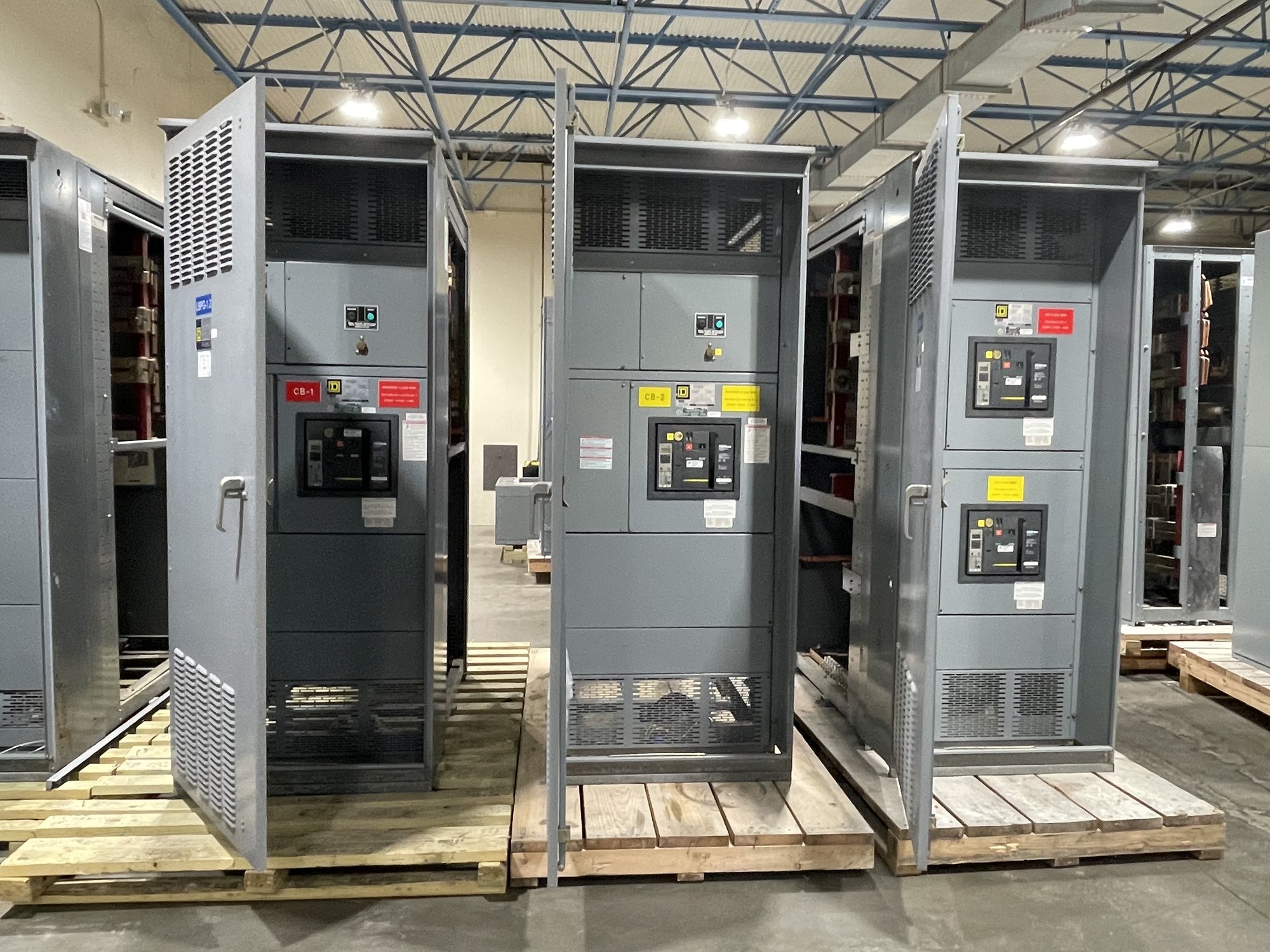
Start with the grounding arrangement
A transfer switch changes the load connection from one source to another. Whether it must also switch the neutral depends on the system’s grounding and bonding design. In a solid-neutral arrangement, the sources share a continuous neutral through the transfer equipment. In a switched-neutral arrangement, the neutral changes with the phase conductors, isolating the load-side neutral from the source not serving the load. Neither arrangement is universally correct; the system design establishes the requirement.
The key distinction is often whether the alternate source is treated as a separately derived system and where its neutral-to-ground bond is located. A generator or other alternate source may have a bonding arrangement that affects whether a continuous neutral could create parallel paths for neutral current. The project engineer should determine the system classification and bonding method from the applicable design documents and governing requirements, rather than selecting a neutral configuration by habit.
Compare source configurations
For a utility-to-generator installation, gather the one-line diagram, source grounding details and generator neutral-bond information. Confirm whether the transfer equipment is open-transition, closed-transition or another arrangement, and identify which conductors transfer. Transition behavior can affect the neutral connection and the sequence in which sources are connected or isolated; the equipment configuration must match the engineered operating scheme.
With two utility sources, multiple generators, or a more complex arrangement, document each source’s grounding point and how the system prevents unintended neutral-current paths. A shared neutral may be appropriate in one design and unsuitable in another. Do not infer the answer from source names, voltage, or the presence of a generator alone. Have the responsible engineer resolve the grounding topology and transfer sequence before the equipment is specified.
Define what the neutral pole must do
When neutral switching is required, specify the intended neutral operation alongside the phase switching. Clarify whether the neutral is switched with the phases, whether the design requires overlapping or non-overlapping neutral contact behavior, and how the transfer sequence is coordinated. These details are design-dependent; the equipment supplier needs the approved functional requirements rather than an assumption that every switched-neutral application uses the same contact arrangement.
Also provide system voltage, phase and wire count, ampere rating, available fault-current information, enclosure and installation conditions, and the applicable control and interlocking requirements. Identify whether the neutral must be full-rated or otherwise sized under the project design, and provide any relevant load characteristics. Do not rely on a generic catalog description to establish suitability: ratings and construction must be confirmed for the specific assembly and application.
Resolve coordination and review early
Neutral switching affects more than the pole count. It can influence the grounding and bonding details shown on drawings, the generator connection, protection and control coordination, and field terminations. Ask the electrical engineer to review the one-line, grounding details, transfer sequence and equipment submittal as a coordinated set. The authority having jurisdiction reviews the project under the applicable requirements; equipment selection alone does not establish approval or code compliance.
Check that the specified transfer equipment can accommodate the intended neutral arrangement and the project’s electrical and mechanical requirements. Confirm terminal provisions, conductor entry, control interfaces and maintenance clearances against the actual installation. If documents conflict—for example, if the one-line shows a switched neutral but generator notes show a different bonding scheme—resolve the discrepancy before release for manufacture. A late change can affect the configuration, drawings and schedule.
Prepare a complete quotation package
For a manufacturer quotation, share the latest one-line diagram, grounding and bonding narrative, source data, transfer sequence, and the engineer’s stated neutral-switching requirement. Include equipment ratings, enclosure and mounting details, control voltage and interface requirements, project specifications, and any required submittal format. State whether the neutral must switch and describe the required contact behavior; if the design decision is still open, identify the engineer responsible for resolving it.
For Georgia projects, include the delivery destination, receiving constraints, requested delivery window and coordination milestones. We build new transfer and switchgear equipment in the United States and can configure equipment to project requirements; exact scope, component availability and schedule are confirmed for each order. Nationwide shipping can support delivery to Georgia, but the project team should coordinate receiving, unloading, storage and installation planning with its selected logistics and electrical professionals.
Close the design loop before release
Before approving drawings, verify that the neutral arrangement shown in the transfer equipment matches the grounding design at both sources and the load. Confirm the intended switching sequence, neutral bonding locations, conductor terminations and any required interlocks with the engineer of record. Record the approved configuration in the procurement documents so the manufacturer, installer and commissioning team are working from the same design basis.
The practical next step is to send the one-line diagram and grounding details with a clear statement of the proposed source arrangement and neutral operation. Ask the project engineer to confirm whether a solid or switched neutral is required, then request equipment configured to that decision. This keeps quotation, submittal review and Georgia delivery planning tied to the actual system rather than an assumed standard arrangement.