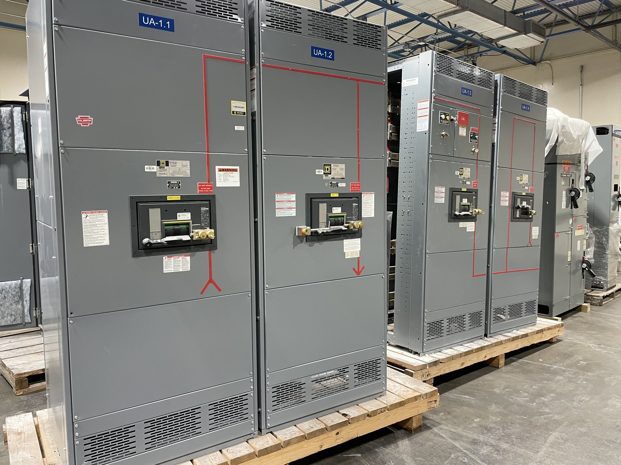
Locate the bond by source arrangement
A neutral-to-ground connection establishes a relationship between the grounded circuit conductor and the equipment grounding system. Its location depends on the source and distribution arrangement; it is not simply a connection to add wherever a neutral bar is present. Bonding decisions influence fault-current paths, protection, and whether downstream neutral and grounding conductors remain separated.
Identify whether the switchboard is supplied by a utility transformer, generator, separately derived transformer, or more than one source. Document which sources have grounded neutrals, how they connect to the distribution system, and whether transfer equipment switches the neutral. Those facts guide engineering review of bond location and help prevent conflicting connections across the system.
Coordinate separately derived sources
A transformer or generator may constitute a separately derived system depending on its electrical connections and transfer arrangement. When it does, grounding and bonding provisions must be coordinated at the source and through the associated distribution equipment. The project engineer should establish the intended system bonding point and grounding-electrode connection, then communicate that design basis to the switchboard manufacturer.
For multiple sources, provide the one-line diagram and describe normal, alternate, and any parallel operating modes. State whether the transfer switch switches the grounded conductor and identify where each source neutral is connected. A switched-neutral arrangement can change which source is connected to the load at a given time; the bond and grounding scheme must be evaluated with that actual operation, not inferred from equipment labels alone.
Keep neutral and equipment ground functions clear
The neutral carries normal load current in grounded systems; equipment grounding conductors provide a path for fault current and ordinarily are not intended to carry normal current. Their bars, enclosures, and connections must be arranged consistently with the approved system design. Downstream bonding that unintentionally joins neutral and equipment ground can create parallel current paths and interfere with grounding and protection functions.
When specifying a switchboard, ask how the neutral bar is to be configured, where the equipment grounding bar is located, and which bonding provisions are required at the service or derived-source point. The answer depends on the system and equipment scope. Do not treat a factory-installed bonding feature as automatically appropriate for every feeder or separately derived source.
Resolve requirements before release
Applicable requirements depend on the installation, adopted electrical code, service conditions, source configuration, and authority having jurisdiction. The engineer of record and relevant utility or inspection authority determine the project requirements; the manufacturer can build to the documented, reviewed configuration but cannot decide the installation design from a general request. UL 891 applies to switchboard assemblies and does not establish a universal bonding scheme or cover medium- and high-voltage switchgear.
Before submittal approval, reconcile the one-line diagram, grounding notes, transfer-switch sequence, and switchboard connection details. Flag any discrepancy between drawings and specifications, especially where a service bond, transformer bond, or switched neutral is shown differently in separate documents. Resolve open items with the responsible engineer before manufacturing release so the assembly and field installation are based on the same design intent.
Provide the details needed for a quote
For a configuration quote, share the project location in Georgia, system voltage and phase, service or feeder role, source types, transfer equipment details, neutral-switching method, grounding notes, and current one-line diagram. Include the required switchboard sections and any specified UL 891 assembly scope. Note who will provide final engineering direction and identify unresolved decisions instead of assuming a bond location.
Also provide requested submittal timing, delivery destination, site access constraints, and the project schedule. American-made components, custom-built configurations, and nationwide shipping can support Georgia projects, but component availability, final scope, and production and delivery timing are confirmed for each order. The project team should coordinate shipping and receiving dates with installation readiness rather than treating a quoted shipment estimate as an installation approval.
Carry the bonding design into handoff
At release and handoff, keep the approved one-line diagram, switchboard drawings, source and transfer sequence, and grounding requirements aligned. The electrical contractor should compare delivered equipment with approved submittals and follow the project’s engineered installation documents. Installation, inspection, testing, and energization belong to qualified personnel under applicable requirements; field changes to bonding should be reviewed by the responsible engineer and authority as required.
Before requesting a final configuration, mark each source, identify the intended bonding point for each operating mode, and confirm whether neutral switching is specified. Send those details with the drawings and delivery schedule. This focused review gives engineering and procurement a concrete basis to resolve open questions before the new switchboard is built and shipped to the Georgia project.