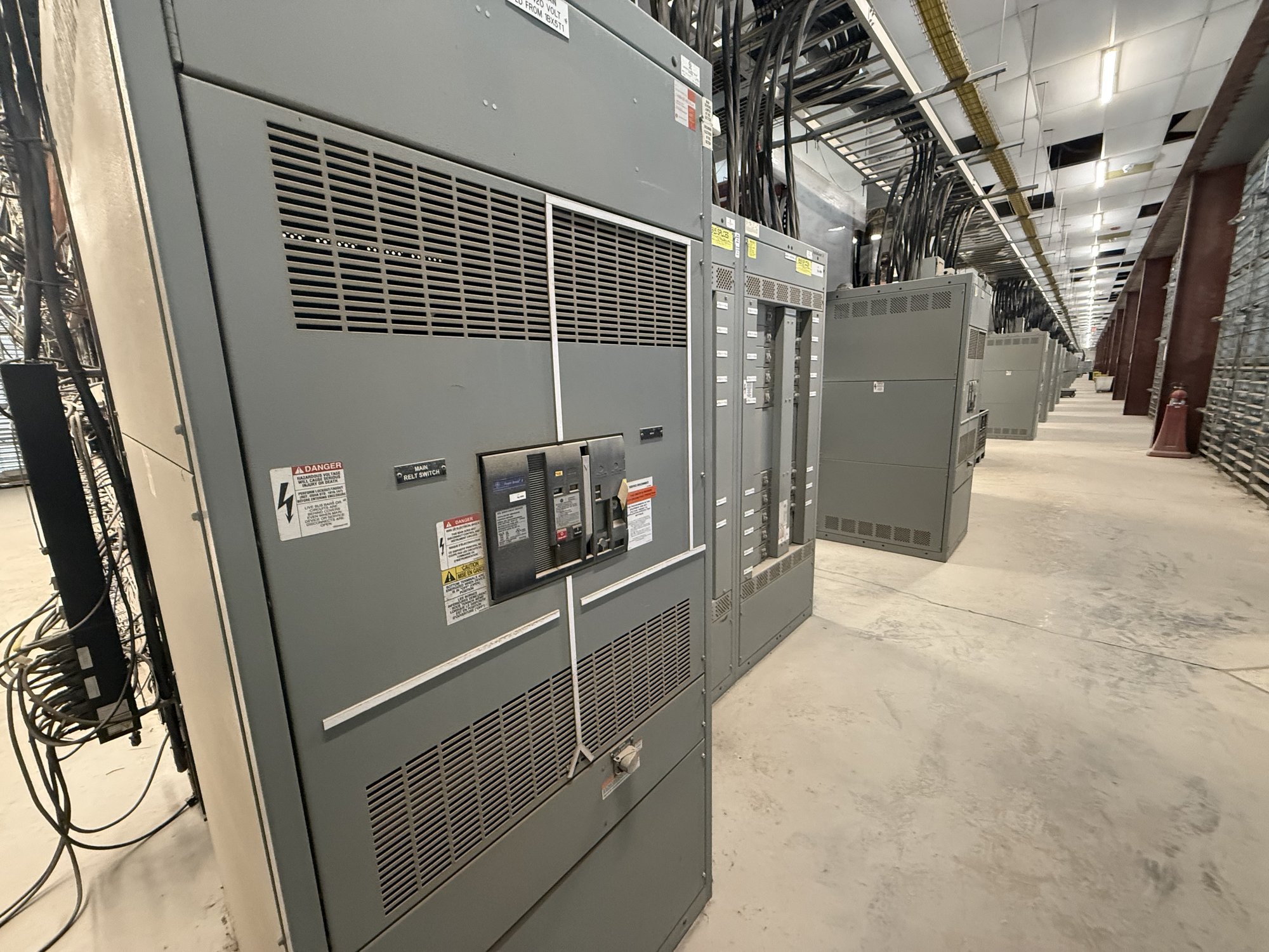
Map distribution to production
Start with how power moves through the plant, not just the service entrance rating. Identify incoming sources, transformers, main distribution points, process areas and major loads such as production lines, pumps, compressors, material handling systems and HVAC. A one-line diagram and load information help establish what the new assembly must distribute and where feeder sections, metering or protective devices may be required.
For facilities with several process areas, review which loads need separate feeders and which operations depend on continuity during maintenance or a fault. Clarify whether the project replaces an existing lineup, adds distribution alongside it, or supports a new building or production cell. These distinctions affect lineup arrangement, connection points, outage planning and coordination with equipment already in service.
Allow for growth without guessing
Production growth can change both the quantity and character of electrical demand. Share planned equipment additions, anticipated process changes and any known limits on floor space or electrical rooms. If future feeders are part of the plan, the design team can evaluate whether provisions belong in the initial configuration; the right approach depends on the documented load forecast, available capacity and physical layout.
Avoid treating unused space as proof of electrical capacity. Breaker positions, bus ratings, fault duty, protective-device coordination and upstream equipment all influence whether a later expansion is feasible. Ask the facility engineer to distinguish documented spare capacity from space reserved for future work, and to identify assumptions that still need confirmation before procurement.
Resolve the specification before release
A useful request for quotation includes the latest one-line diagram, equipment schedules, available fault-current information, system voltage and frequency, grounding method, service conditions and applicable project specifications. Identify required main and feeder devices, trip functions, metering, control interfaces and any integration with generators, transfer equipment or other sources. Missing or preliminary information should be labeled rather than silently treated as final.
Confirm the applicable assembly type and standard with the project engineer. UL 891 applies to switchboard assemblies; it is not a blanket listing for medium- or high-voltage switchgear. Include required drawings, submittals, inspection points and documentation in the procurement scope. Engineering and the authority having jurisdiction must review the design and installation for the specific application.
Fit the lineup to the plant
Manufacturing spaces impose practical limits that can shape the assembly: room dimensions, access routes, door and aisle clearances, cable entry direction, overhead services, housekeeping pads and the location of existing conduits. Provide room plans and field dimensions where available, and note any limits on section width, height, depth or handling access. Confirm who is responsible for field measurements and when they become final.
Process environments also merit clear discussion. Identify temperature, dust, moisture, corrosive exposure, vibration or other site conditions that could affect enclosure selection and installation planning. Share maintenance access needs and operating constraints, including any planned outage windows. The configuration and environmental provisions must be established from the actual site conditions, not assumed from the facility’s general description.
Coordinate procurement and Georgia delivery
For a quote, provide the project location in Newnan, requested quantity, target in-service date, scope boundary and the current state of engineering. State whether installation, field connections, startup or commissioning are handled under separate contracts. We manufacture new equipment using American-made components, and can develop custom configurations; component availability, final scope and schedule are confirmed for each order.
Georgia delivery planning should account for the receiving location, truck access, unloading equipment, staging space and the route from the receiving point to the electrical room. Tell us about dock restrictions, delivery-hour limits, security procedures and whether sections need to move through narrow corridors or lifts. Shipping arrangements and timing are coordinated against the project’s confirmed equipment configuration and site requirements.
Make handoff useful to operations
Before release, align the approved drawings with feeder destinations, device functions, labeling conventions and the facility’s documentation practices. Confirm who will review submittals, resolve design questions and approve changes that affect loads or connections. A clear responsibility matrix helps prevent procurement assumptions from becoming field changes after the assembly is built.
Bring the one-line diagram, load and growth assumptions, site dimensions, environmental conditions and delivery constraints together for the quote request. Mark unresolved items and identify the engineer responsible for final decisions. That focused package gives the project team a practical basis to define process distribution for a Newnan manufacturing facility and coordinate the next design and procurement steps.