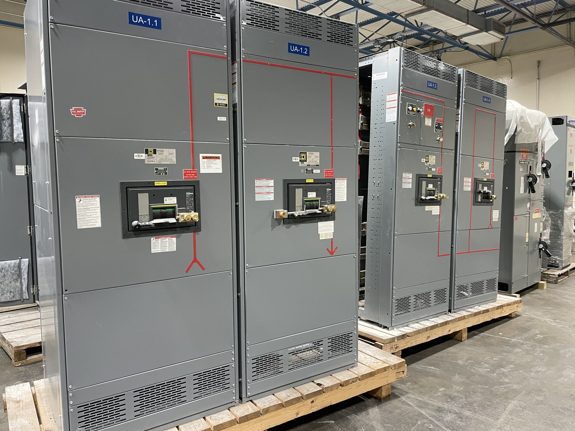
How the arrangement works
A main-tie-main lineup has two incoming main devices, each serving a bus section, and a tie device connecting those sections. With the tie open, the buses operate separately and each source supplies its assigned section. Closing the tie can connect the buses so one available source may serve loads on both sections, subject to the equipment and system design.
This arrangement does not itself detect an outage or guarantee uninterrupted power. Transfer may be manual or controlled by an engineered automatic scheme, and the sequence must account for source status, interlocks and load priorities. Specify whether transfer is intended for planned maintenance, loss of a source, or another operating condition; those use cases affect control logic and operating procedures.
Choose normally open or normally closed
A normally open tie is common when each source ordinarily serves its own bus. If one source is lost, the tie may be closed after the affected main is opened, allowing the remaining source to carry selected or all loads if it has adequate capacity. This can limit parallel operation, but it does not remove the need to verify loading, protection and transfer sequence.
A normally closed tie keeps the bus sections connected during normal operation. That choice can change how sources share load and how protective devices respond to faults. Parallel operation is not appropriate by assumption: confirm source synchronization, grounding, utility or generator operating requirements, protection coordination and permitted operating modes with the project engineer and relevant authorities.
Interlocks and transfer sequence
For a scheme that must prevent two sources from being connected together, specify the required mechanical and electrical interlocks and the permitted device positions. A typical sequence may require opening the failed-source main before closing the tie. Whether the sequence is open-transition, closed-transition or strictly non-paralleling must be explicit; control descriptions such as “automatic transfer” alone do not define it.
Identify who initiates transfer, what conditions inhibit it, how the operator sees source and device status, and how restoration to normal service occurs. Generator start and cooldown signals, time delays, load shedding, remote commands and manual bypass provisions may be relevant. The control narrative and one-line diagram should agree, and qualified personnel should review operating and maintenance procedures before energization.
Source capacity and fault-duty limits
When the tie is closed, a source may be expected to feed loads beyond its normal section. Compare that contingency load with the source’s continuous capacity, generator capability where applicable, transformer loading and feeder limits. Identify essential loads and any planned shedding. A transfer that is mechanically possible may still overload a source or produce unacceptable voltage conditions.
Fault current must be evaluated for each intended operating configuration, including separate-bus operation, tie-closed operation and any source-paralleling mode. Available fault current, protective-device interrupting ratings, bus withstand and coordination can differ between these cases. Provide the study basis or design values for review; do not select ratings from normal load current alone. UL 891 applies to switchboard assemblies, not as a blanket certification for medium- or high-voltage switchgear.
Define the assembly for procurement
For a quote, share the project one-line diagram, system voltage and phase, source types and capacities, bus arrangement, main and tie device requirements, load data, and known available-fault-current values. Include the intended normal tie position, transfer sequence, interlocking philosophy, control power, metering, communications and any required future provisions. Identify the project schedule, delivery location in Georgia and site access constraints.
Also clarify whether the requested scope is a UL 891 switchboard assembly, what incoming and outgoing devices are included, and which engineering documents or submittals are needed for review. We build new equipment in the United States using American-made components where specified, and can develop custom configurations. Exact scope, component availability and schedule are confirmed for each order; do not assume a standard lineup fits the one-line or site.
Coordinate delivery and handoff
Georgia delivery should be planned around the installation sequence, receiving capability and site conditions, not just the shipment destination. Confirm the receiving address, unloading arrangements, access route, storage conditions and required delivery window early. Nationwide shipping supports projects across Georgia, while the confirmed order scope and schedule determine the actual shipment plan.
Before release, have the engineer, facility team and purchasing lead reconcile the approved one-line, control narrative, device ratings, normal operating state and fault-study assumptions. Record who approves changes and how revised drawings are handled. For a quote, send the available diagrams and transfer requirements together, flag open engineering decisions, and state the Georgia delivery site and target project dates so the proposed configuration can be reviewed against the intended operation.