Define the operating arrangement
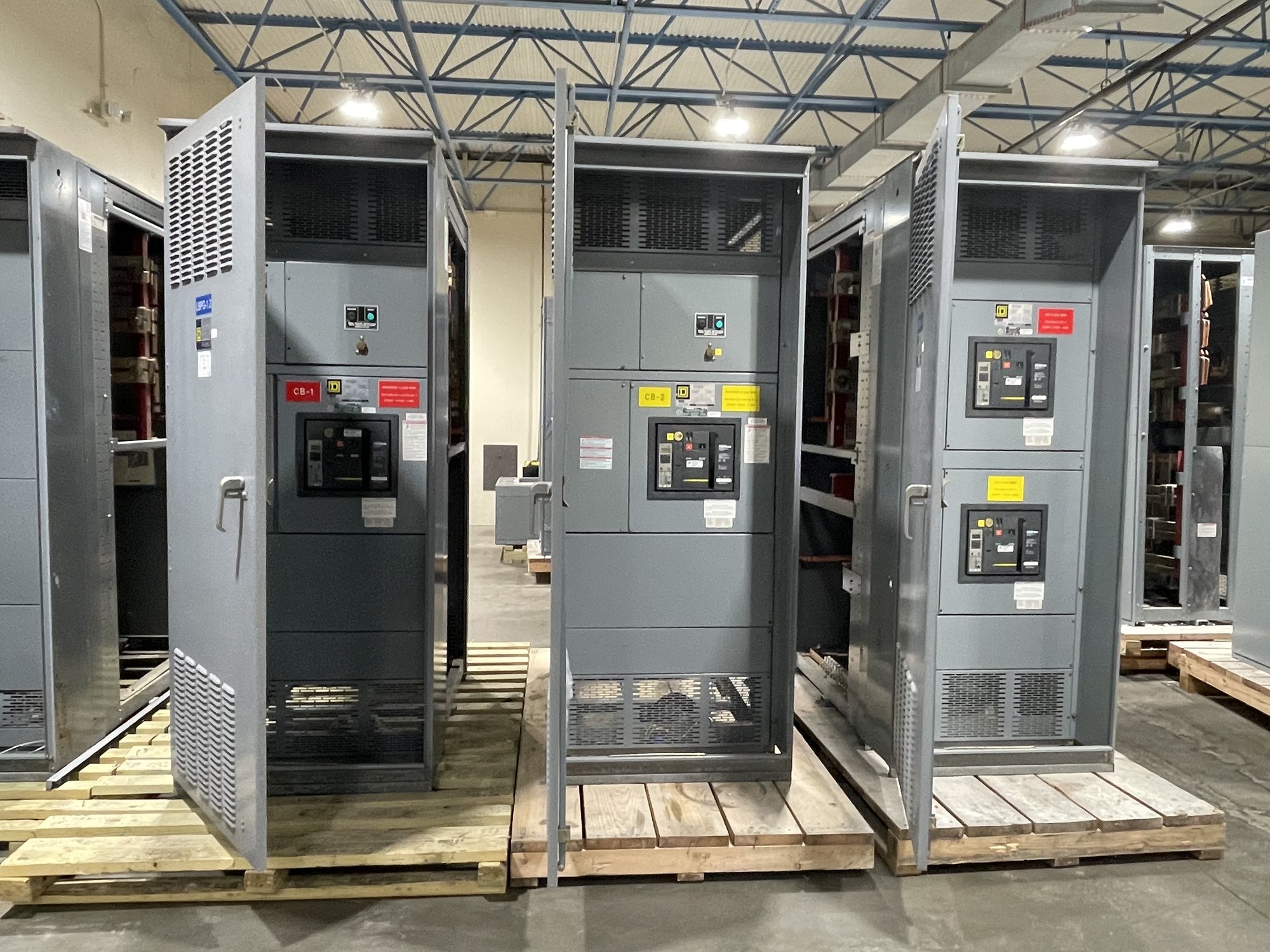
A typical arrangement has an incoming main breaker for each bus section and a tie breaker between them. With the tie open, each source serves its own section; when one source or main is unavailable, an approved operating sequence may allow the remaining source to feed both sections through the tie. This configuration can support planned maintenance and selected contingencies, but it does not itself guarantee uninterrupted service.
Start with the normal state: mains closed and tie open, one source carrying both sections with the tie normally closed, or another engineered scheme. Identify whether transfer is manual, automatic, or supervised, and what events initiate it. The answer affects controls, protective coordination, source capacity, operating procedures and the way operators verify the lineup state.
Set boundaries on source paralleling
Two incoming sources must not be assumed suitable for parallel operation. If the operating concept requires closing both mains and the tie, engineers must evaluate source synchronization, utility restrictions, generator controls, fault contribution and protection. Many schemes instead use an open-transition sequence: open the affected main, verify its position, then close the tie, avoiding intentional overlap between sources.
Specify the permitted breaker combinations and required interlocking accordingly. Mechanical interlocks can prevent certain simultaneous breaker closures; electrical interlocks and control logic can add permissives, status checks and transfer conditions. The design should make clear how it behaves with a failed control-power supply, a breaker that does not reach its commanded position, or conflicting operator commands. Interlock details depend on the selected equipment and engineered sequence.
Match loads to available capacity
When one source feeds both bus sections, its capacity and the path through the tie must support the transferred load. Compare the expected emergency or maintenance load with the source rating, breaker ratings, bus ampacity and any applicable derating. Identify loads that must remain on each section and loads that can be shed; otherwise a seemingly useful transfer arrangement may exceed the available capacity or disrupt priority equipment.
Provide load schedules with normal and contingency demand, major motor starting information, sensitive loads, and any planned future additions. The electrical engineer should assess short-circuit duty, protective-device coordination and ground-fault requirements for each credible configuration. A double-ended lineup may produce different fault levels and current paths depending on which mains and tie are closed, so one operating state cannot stand in for the full study.
Specify the physical lineup
Describe the incoming source characteristics and the required sections, mains, tie, metering, protection, controls and cable or bus connections. Clarify where feeders land, how the lineup interfaces with transformers or generators, and what room access and working-space constraints apply. The tie section’s position and the arrangement of incoming compartments can affect cable routing, maintenance access and the physical sequence of installation.
For a new UL 891 switchboard assembly, confirm that the requested assembly scope and ratings are applicable to the project. UL 891 applies to switchboards; it is not a blanket listing for medium- or high-voltage switchgear. Voltage class, construction, interrupting and withstand requirements, enclosure, environmental conditions and control features must be established for the specific design rather than inferred from the double-ended description.
Plan procurement and project handoff
For a useful quotation, share one-line diagrams, source details, normal and contingency operating sequences, load data, fault-current information, space constraints and required interface points. Include preferred interlock behavior, transfer controls, metering, communications and documentation needs. Flag whether utility or generator sources can operate in parallel, who owns transfer logic, and which party will provide settings and final engineering review.
For Georgia projects, coordinate delivery around the receiving site’s access, unloading capability, installation sequence and required ship-to point. Nationwide shipping is available, while configuration scope, component availability and schedule are confirmed for each order. Before release, align the approved drawings, connection details, control sequence and responsibility for field verification among the manufacturer, project engineer, contractor and facility team.
Turn the sequence into an operating plan
A sound specification connects each permitted breaker state to a clear operating purpose, capacity check and interlock response. Ask the project engineer to document normal operation, maintenance transfer, restoration to normal, abnormal conditions and any required load shedding. Ensure operators receive procedures consistent with the final controls and that qualified personnel handle installation, testing and energization under the project’s approved requirements.
Before requesting pricing, mark the one-line with the intended normal state and each transfer state, then list the conditions that must block or permit a tie closure. That focused package helps resolve whether the proposed arrangement fits the sources, loads and site constraints before equipment details are finalized.