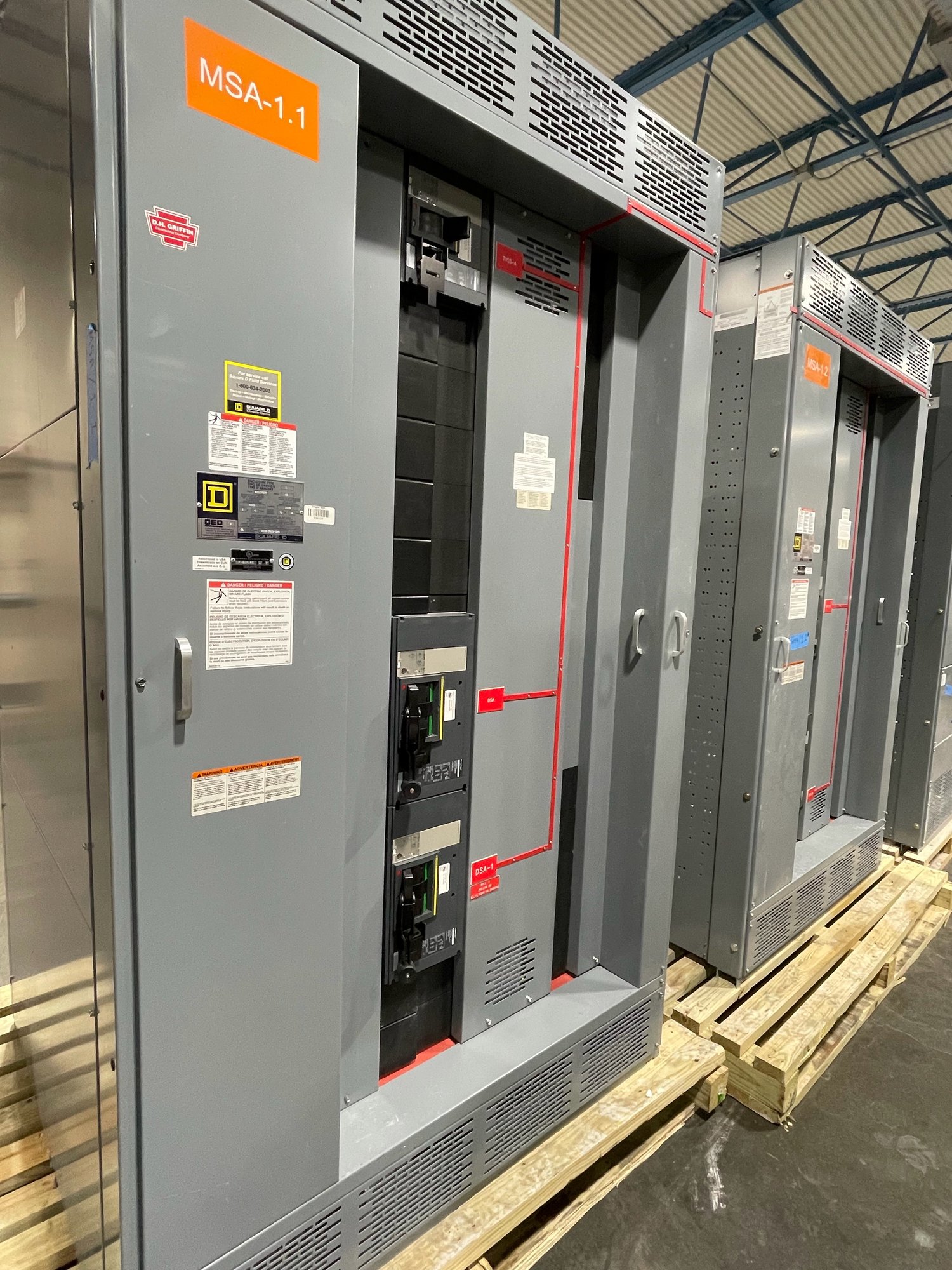
What main-lug-only means
A main-lug-only, or MLO, switchboard has incoming line connections at its main lugs but no integral main circuit breaker or switch. The assembly distributes power through its branch or feeder devices; it does not provide a main disconnect within the board. The service or feeder arrangement therefore determines where the supply is controlled and protected.
MLO construction may suit a feeder-fed distribution point when an upstream device provides the required overcurrent protection and disconnecting means for the installation. It can also affect layout, cost, available space and maintenance planning. Those benefits depend on the one-line diagram and applicable rules, so an MLO configuration should be selected as an engineered arrangement rather than as a default.
Establish the upstream device’s role
Identify the exact upstream breaker or fused switch, its location, frame and trip characteristics, and the conductors between it and the switchboard. Verify that the device is intended to protect those conductors and the downstream assembly under the applicable design and installation requirements. A protective device elsewhere in the system is not automatically adequate simply because it is upstream electrically.
Confirm whether the switchboard is service equipment or a downstream feeder assembly. Service disconnect requirements, grounding and bonding details, and permitted device locations can differ from feeder applications. Have the project engineer and authority having jurisdiction review the proposed arrangement. The manufacturer needs the approved one-line and protection assumptions to build to the intended scope; it cannot establish site compliance from a brief equipment description.
Check fault current and coordination
Provide the available short-circuit current at the switchboard and the upstream device’s interrupting rating, settings or fuse data. The equipment short-circuit current rating and the protective-device combination must be evaluated for the actual system. Do not infer an acceptable rating from a nominal voltage or from the presence of a breaker. If series ratings or tested combinations are proposed, document the specific devices and confirm the applicable conditions with the engineer.
Ask whether selective coordination, arc-flash analysis or other project studies impose requirements on trip settings and device selection. Those studies may limit which upstream protective device can serve the board, even when its ampere rating appears suitable. Coordinate the study assumptions with the equipment schedule and final submittal so that a later device substitution does not undermine the design.
Define the board and feeder scope
Specify system voltage, phase and wire count, bus ampacity, neutral requirements, grounding provisions, enclosure and environment, incoming conductor quantity and size, and the number and type of outgoing devices. State whether conductors enter from the top or bottom and identify cable or busway connections. These details determine the required lug arrangement, wiring space and section layout; an MLO designation alone is not enough to define an assembly.
Clarify whether a separate disconnect is required near the board or at another point, and who supplies it. Include the upstream device make and model when selected, or clearly mark it as by others when it remains outside the manufacturer’s scope. New switchboards are custom-configured to the approved project requirements; UL 891 applies to switchboard assemblies, not as a blanket listing for medium- or high-voltage switchgear.
Resolve procurement and delivery details
For a quotation, share the one-line diagram, equipment schedule, site voltage and fault-current information, upstream protective-device data, required ratings, connection details, preferred arrangement and submittal requirements. Identify any alternates, field constraints, delivery destination in Georgia and the date the equipment must be available for installation. These inputs help clarify scope and reveal missing engineering decisions before order release.
American-made components, custom configurations and nationwide shipping can support Georgia projects, but exact component availability and schedule are confirmed for each order. Coordinate delivery with receiving access, unloading capability, storage conditions and the construction sequence. Establish who reviews drawings, approves deviations and confirms that the selected upstream device matches the released design.
Close the design gap before release
Before procurement approval, have the responsible engineer verify the upstream protective device, feeder conductors, equipment ratings, disconnect location, grounding and bonding, and any study-driven coordination requirements. Resolve open items on the one-line and equipment schedule rather than relying on a general note that the board is MLO. Final installation and energization should be handled by qualified personnel under the approved plans and applicable authority review.
For a project quote, send the current one-line, the upstream device details, board schedule, fault-current basis and Georgia delivery requirements together. Flag anything not yet selected, such as breaker settings or conductor entry, so it can be identified as an open coordination item. Reconcile approved submittals with the field installation before release and again before energization.