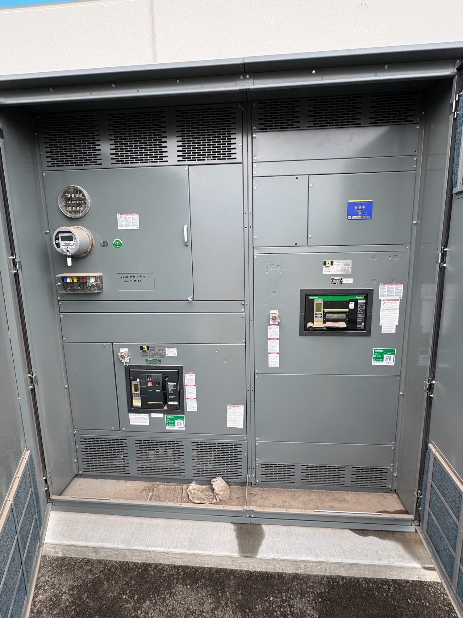
What the integral main breaker does
The main breaker is the switchboard’s incoming overcurrent protective device and disconnecting means when the approved design assigns it that function. It can interrupt current under specified conditions and provide a means to isolate the switchboard from its supply. Its placement at the line side of distribution devices distinguishes a main-breaker arrangement from a main-lugs-only configuration, where the incoming conductors terminate at lugs and the required upstream protection is addressed elsewhere in the system.
Downstream feeder breakers or other protective devices serve individual circuits leaving the switchboard. The main breaker does not replace feeder protection, nor does its presence by itself establish protection for every load. The engineer must coordinate the main and feeder devices with the source, conductors, fault current, load characteristics and applicable project requirements. The final one-line diagram and equipment submittal should make those relationships clear.
Specify the rating in context
A main breaker’s current rating is one part of its specification, not a complete description of suitability. The design team must determine the system voltage and phase, required continuous current, conductor and bus arrangements, available fault current, and the breaker’s interrupting and withstand-related requirements as applicable to the selected assembly. These values come from the project’s electrical design and source information, not from a generic switchboard default.
The service rating, main-device rating and switchboard bus rating need to be evaluated together. They may be related, but they do not automatically mean the same thing or establish the permitted load. The engineer should confirm the intended service and distribution design, including any applicable conductor, overcurrent, demand and utility requirements. Do not assume a larger main breaker is a simple future-proofing upgrade; it can affect protection, conductor coordination and the complete assembly configuration.
Coordinate service and feeder protection
Protection coordination determines how the main device and downstream devices respond to overloads and faults. Depending on the system, the design may require selective coordination analysis, settings review or other evaluation. Breaker trip functions, frame and sensor selections, available settings and device characteristics can affect that work. Do not infer coordination performance from a device’s ampere rating or from a single-line drawing that omits relevant protective-device information.
The main breaker also has to be considered against the source and service arrangement. Confirm whether the supply is utility-fed, generator-fed or part of another engineered system, and identify any transfer equipment, parallel sources or other devices that affect the incoming path. The utility’s service requirements and the authority having jurisdiction may impose project-specific conditions. The responsible engineer and relevant authorities must review the complete design; no generic configuration alone establishes approval or code compliance.
Plan the physical arrangement
An integral main breaker takes space and can influence section layout, cable entry, access and the sequence of distribution sections. Share the intended line-side and load-side cable approach, room constraints, working clearances, environmental conditions and any known routing restrictions. Identify whether the switchboard must connect to existing equipment, a transformer, a generator or a separate distribution lineup. These details help determine whether the proposed arrangement can be developed around the actual installation.
Feeder count and expected circuits matter as well. Provide the planned feeder-device types and ratings where established, spare or future provisions, metering needs, control requirements and any required barriers or compartment arrangements. If the project has a defined footprint or shipping path, provide those dimensions and constraints early. Final dimensions, conductor spaces and section details must be confirmed against the engineered configuration and approved submittals rather than assumed from a preliminary selection.
Prepare a useful quote request
For a focused quote, provide the latest one-line diagram, system voltage and phase, service and bus requirements, main-breaker rating and available fault-current information, plus the feeder schedule. Include known protective-device requirements, metering or control functions, cable-entry preferences, physical limits and the project schedule. If some values remain undecided, identify them as open engineering items instead of presenting estimates as confirmed design data.
Also state the project location in Georgia, delivery destination, site access or receiving constraints, required submittal milestones and the date equipment is needed on site. This allows shipping and order planning to be considered alongside the build configuration; exact scope, availability and timeline are confirmed for each order. We manufacture new, custom-built switchgear assemblies in the United States, with American-made components and nationwide shipping options subject to the specified scope and order details.
Carry the design through handoff
Before release, compare the approved submittal against the one-line diagram, service requirements and feeder schedule. Resolve discrepancies in main-device rating, device functions, bus details, cable access, metering, dimensions and delivery assumptions. Confirm who is responsible for engineering decisions, utility coordination, authority review, installation planning and field connections. Only qualified professionals should install, inspect, service or energize the equipment under the project’s approved procedures.
For a Georgia project, make the next step a coordinated equipment review: send the current one-line, service data, feeder schedule, site constraints and required delivery date, then flag unresolved design choices. This gives the manufacturer a concrete basis to develop a main-breaker configuration for review while keeping protection, service interfaces and downstream distribution tied to the project engineer’s requirements.