Start with the plant’s motor profile
A plant load list should distinguish large motors from smaller, general-purpose loads. For each motor, share horsepower or kilowatts, voltage, full-load current, starting method, duty, and whether it runs continuously or intermittently. Identify across-the-line starters, reduced-voltage starters, soft starters, and variable-frequency drives; these choices affect feeder arrangements, protective devices, controls, and space requirements.
Also describe how the process operates. A motor that starts rarely may present different coordination and operating concerns from a critical pump, compressor, conveyor, or fan that starts frequently or must restart after an outage. Tell us which loads must run together, which may be shed, and whether future motors or process expansion are anticipated. The engineer can use that context to develop the equipment schedule and one-line requirements.
Establish available fault current at the connection
Switchgear selection depends on the prospective short-circuit current at its point of installation, not simply on a plant’s normal operating load. Provide the latest utility fault-current information for the service point and identify transformer size, impedance, voltage, and connection where known. For an existing facility, include relevant changes such as added transformers, generators, or parallel sources that may affect the calculation.
Ask the project engineer to confirm the available-fault-current study, protective-device coordination, and required equipment ratings for the actual system configuration. Motor contributions, alternate feeds, and operating modes can influence the analysis. Do not rely on a rating copied from an older lineup or assumed from a similar plant; the responsible engineer and authority having jurisdiction must review the design and its application.
Define the equipment and operating arrangement
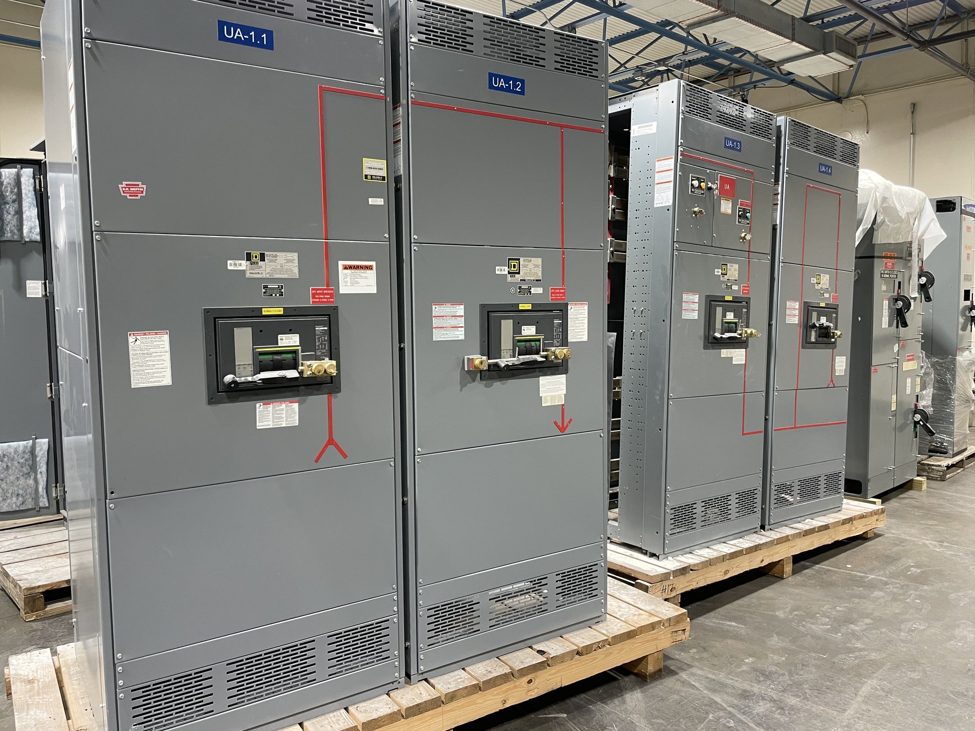
Clarify whether the scope calls for service or distribution switchgear, motor feeders, a UL 891 switchboard assembly, or a combination of equipment. UL 891 applies to switchboards; it is not a blanket listing for medium- or high-voltage switchgear. Share system voltage, phase and wire configuration, bus arrangement, incoming source details, feeder count, and the functions required for each outgoing circuit.
Protection and control requirements should follow the project design rather than a generic package. Identify desired metering, trip or alarm functions, interlocks, communications, and control-power arrangements, and provide the applicable drawings and specifications. Confirm enclosure type, cable entry direction, available room, working clearances, and access route with the site team. Final ratings, construction, and certification scope are confirmed for each order.
Resolve site and installation constraints early
Valdosta project teams should check the actual installation environment before the equipment layout is fixed. Report indoor or outdoor placement, ambient and moisture conditions, dust or corrosive exposure, elevation if relevant, and any washdown or process-area restrictions. Give the available footprint, ceiling height, cable trench or conduit locations, and the route from receiving area to the final equipment position.
Existing plants can impose constraints that are easy to miss in a one-line diagram: shutdown windows, limited access, equipment that must remain energized, or connections to legacy gear. Identify these conditions and the responsible installation contractor early. Switchgear is built for the confirmed scope; installation, testing, and energization should be planned and performed by qualified personnel under the project’s engineering and safety procedures.
Make procurement and Georgia delivery predictable
For a quote, send the one-line diagram, load list, fault-current basis, equipment specification, and requested schedule. Include motor starting and drive details, feeder requirements, control and metering needs, enclosure conditions, and any approved deviations. If some information is pending, mark it clearly and identify who will provide it; unresolved inputs can change configuration, pricing, and production timing.
We build new equipment in the United States using American-made components, with custom configurations and nationwide shipping. For delivery to a Valdosta site, coordinate the required delivery point, receiving hours, unloading capability, access restrictions, and sequence relative to construction milestones. Exact scope, component availability, and shipment timing are confirmed for each order rather than assumed from a general schedule.
Hand off a complete project basis
Before release for manufacture, align the equipment schedule, approved drawings, interface points, and open technical decisions among the plant engineer, electrical contractor, and purchasing team. Confirm which party owns utility coordination, final fault-current calculations, field measurements, and review by the authority having jurisdiction. This handoff reduces the risk of mismatched feeder counts, control interfaces, or site dimensions.
To begin a Valdosta industrial plant quote, provide the motor list, current one-line, available-fault-current documentation, site and delivery constraints, and target project milestones. Flag planned load growth and any critical motors that cannot tolerate an interruption. With those details, the equipment scope can be evaluated against the project’s engineering basis and refined before procurement.