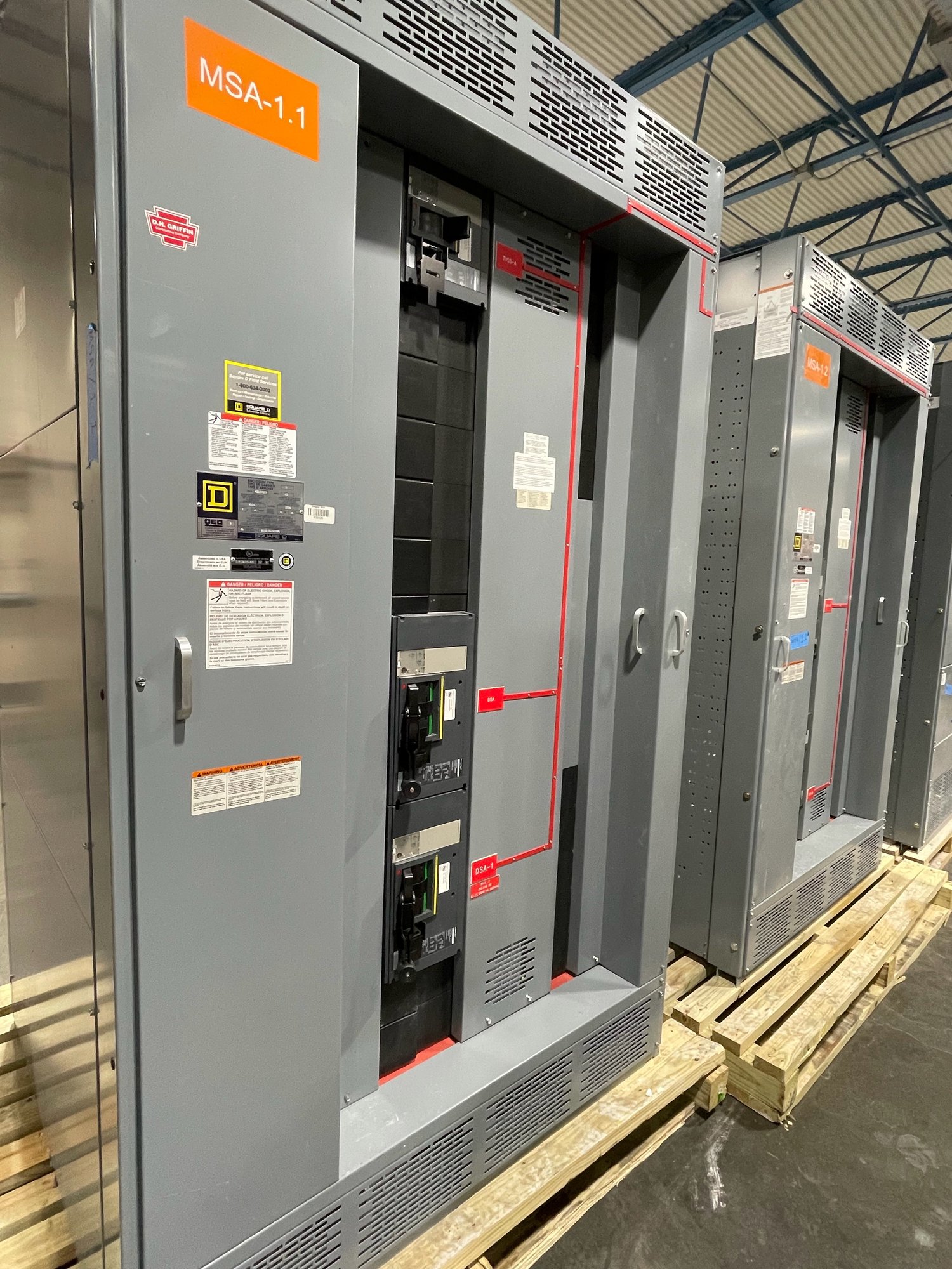
Start with the plant load profile
A plant’s electrical demand is shaped by more than total connected load. Document motor horsepower, voltage, full-load current, starting method, duty cycle and the frequency of simultaneous starts. Include pumps, compressors, conveyors, fans, process heaters, welders and other loads whose operation can create high starting current or rapid load changes. This information helps engineers evaluate feeder and bus requirements, switching arrangements and space for future circuits.
Identify how loads are grouped by process area and which equipment must remain available during planned maintenance or an interruption. Note standby generation, alternate sources, transfer schemes, power factor correction and any variable-frequency drives that affect the distribution design. A clear load schedule and current one-line diagram give the manufacturer and project engineer a practical basis for defining equipment scope; assumptions should be resolved before configuration is finalized.
Define continuity and operating needs
Process continuity requirements should be stated in operational terms. Identify loads that may stop without consequence, loads that require a controlled shutdown, and loads whose interruption can damage product, equipment or the process. Explain whether operators need access to individual feeders, whether maintenance must occur with adjacent sections energized, and how the plant intends to isolate equipment. These needs influence the arrangement and should be reviewed by the responsible electrical engineer.
Consider how the plant will operate during source loss, maintenance, or a change in production. If the project includes multiple incoming sources, bus ties or generator connections, provide the intended operating sequence and any restrictions on paralleling. Do not assume that a particular lineup or transfer method is appropriate based on a brief description. The final design depends on the electrical study, operating procedures, equipment scope and review by the project’s qualified professionals.
Coordinate protection with available fault current
Fault coordination is essential where a trip can interrupt several process areas or leave critical equipment without power. Share available fault-current information at the proposed connection point, upstream protective-device data, grounding arrangement and any known changes to the utility or plant source. The engineer can use these inputs to study selective coordination, short-circuit duty and protective-device settings across the distribution system. Equipment selection and settings must be based on applicable study results, not on an assumed fault level.
Ask which devices and settings are included in the project scope, who will provide the coordination and arc-flash studies, and what documentation is needed for final review. A change in transformer size, generator contribution, feeder length or upstream device can affect study conclusions. UL 891 applies to switchboard assemblies; it is not a blanket listing for medium- or high-voltage switchgear. Confirm the required equipment type, applicable standards and approval path with the engineer and authority having jurisdiction.
Account for the industrial environment
Describe the actual installation location rather than relying on a broad label such as plant floor. Provide indoor or outdoor placement, ambient temperature range, humidity, dust, corrosive vapors, washdown exposure, vibration and altitude when known. Explain whether the equipment is near process machinery, subject to frequent cleaning, or installed in a controlled electrical room. These details affect enclosure choices, access, layout and the suitability of proposed components; the manufacturer needs project-specific conditions before confirming a configuration.
Room drawings are equally important. Share available wall and floor space, ceiling height, access routes, door dimensions, cable entry direction, conduit locations and required working clearances for review. Consider how sections will be moved into place and whether future service access is practical. The engineer and installation team must verify the final arrangement against site conditions and applicable requirements; a drawing review cannot replace field verification or approval by responsible authorities.
Make procurement and delivery information usable
For a quote, provide the one-line diagram, load schedule, system voltage and frequency, source details, known fault-current data, feeder count, device functions, metering needs, enclosure conditions and requested documentation. Include the project phase, required submittal dates, target shipment window and any defined hold points. State whether the scope includes a UL 891 switchboard assembly, other switchgear, or both, so equipment boundaries and standards can be reviewed accurately. Final scope, component availability and timeline are confirmed for each order.
Georgia delivery planning should account for the plant’s receiving hours, unloading equipment, delivery access, staging area and route from the receiving point to the electrical room. Confirm who accepts the shipment, who checks it for transit damage and how the installation contractor will sequence placement with other work. We build new equipment in the United States and ship nationwide; project-specific shipping arrangements and dates are confirmed during order planning rather than assumed from the destination alone.
Prepare a clean project handoff
Before release, align the approved drawings, device schedules, labels, accessories and scope exclusions with the plant’s design and procurement teams. Identify who reviews submittals, resolves comments, confirms final settings and authorizes changes. Record open technical questions early, especially around motor starting, source arrangements, future feeders and environmental conditions. A disciplined review reduces ambiguity between the manufacturer’s supplied equipment and field wiring, studies, installation and commissioning responsibilities.
To begin a focused quotation, send the latest one-line diagram and load information with the site conditions, delivery constraints, required equipment standards and project dates. Flag the motors or process loads that cannot tolerate an interruption and explain the intended operating sequence. That information lets the project team evaluate a configuration around the plant’s actual distribution needs and confirm scope, availability and schedule for the Georgia installation.