Define how the generator sources will operate
Start with the intended operating sequence. Generators may start together to serve a planned load, start in stages as demand rises, or operate in standby arrangements where a utility interruption initiates a defined transfer sequence. The required sequence affects breaker arrangement, control logic, interlocks and the information operators need at the switchgear. Describe normal, emergency and test modes rather than relying on a general statement that the generators will run in parallel.
Provide the generator count, each unit’s nameplate data, output voltage and frequency, and whether the units are identical or differ in capacity or controls. Explain which sources may operate together and whether the system must accommodate a unit unavailable for maintenance. These details help establish the bus arrangement and identify operating cases for engineering review; they do not, by themselves, determine a final rating or approve a design.
Specify synchronization and breaker control
Before a generator breaker closes onto an energized bus, the control scheme must establish that the source is suitable for connection. The project specification should identify the intended synchronization method and the signals or equipment available from each generator controller. Relevant considerations include voltage, frequency, phase relationship, breaker status and the sequence for permissive, close and post-close control. Confirm who supplies each function and where control responsibility passes between generator packages and paralleling gear.
Clarify whether the bus is normally dead before the first generator closes, remains energized by another source, or can be energized under more than one operating condition. Also document manual and automatic operating expectations, local versus remote commands, and what should happen after a failed start or unsuccessful synchronization attempt. These operating details let the manufacturer coordinate control interfaces without assuming a specific generator make, controller or project sequence.
Plan load sharing and load management
When multiple generators share a bus, specify how active and reactive load should be distributed and whether the units should share proportionally to their capacity. The answer can depend on generator controls, communications, plant operating goals and the range of units expected to run together. Identify any required load-management functions, such as starting additional units as demand increases, shedding selected loads when capacity is limited, or restoring loads in stages after a source becomes available.
List major loads and their operating behavior, including large motor starts, variable-frequency drives, sensitive electronic loads and any loads that cannot tolerate interruption. Share the expected demand profile and the priority of essential versus deferrable loads. The engineering team can use this information to coordinate the proposed control scope and review the system’s operating cases. Actual performance depends on the complete generation and distribution design, not switchgear alone.
Coordinate protection and system interfaces
Protection must account for generator sources operating together, the paralleling bus and downstream distribution. Provide available generator protection information, fault-current and coordination studies when available, and the project’s intended protection philosophy. Identify required protective functions and which party is responsible for relays, settings, current transformers, voltage sensing, trip circuits and coordination with generator packages. Final device selection and settings require engineering based on the actual system and applicable review.
Map the interfaces to utility service, transfer equipment, downstream switchboards, building controls, emergency systems and remote monitoring. For each connection, identify the source of status and command signals, communications expectations, cable or terminal responsibilities, and any required alarm points. A clear interface schedule can expose scope gaps early, especially where the generator supplier, electrical contractor and switchgear manufacturer divide responsibilities.
Resolve ratings, construction and procurement inputs
For a quote, share the one-line diagram, generator schedules, system voltage, frequency, available fault-current information, bus requirements, enclosure and installation conditions, and the required delivery destination in Georgia. Include project specifications, control narratives, preferred equipment arrangement and any preliminary studies. If some documents are not complete, identify what is known, what remains open and who will provide the missing information. Exact configuration, availability and timeline are confirmed for each order.
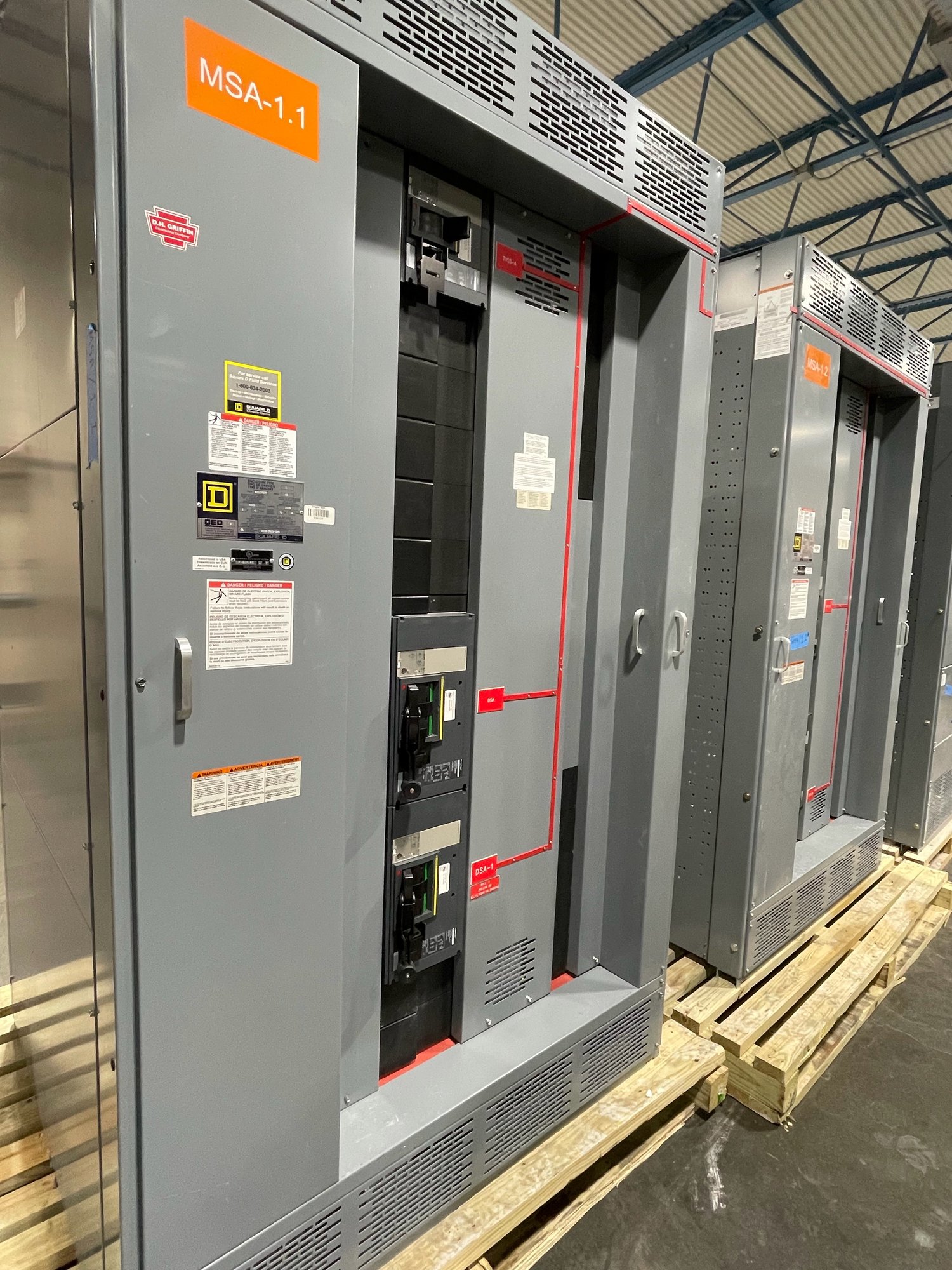
Ask how the proposed assembly will accommodate the required generator breakers, metering, controls, protection and field connections, and identify any dimensions or access constraints that affect the electrical room. UL 891 applies to switchboard assemblies; it is not a blanket listing for medium- or high-voltage switchgear. The applicable construction and certification scope must be established for the actual equipment and project requirements rather than inferred from a general product description.
Carry the sequence through delivery and startup
A useful project handoff includes approved drawings, control narratives, interface schedules, equipment data and a sequence of operation that the generator supplier and installing contractor can review. Set expectations for drawing review, changes, factory documentation and the information needed before release to production. Georgia delivery should be coordinated with the site’s receiving access, unloading plan, installation sequence and construction schedule; shipping arrangements and timing depend on the specific order.
Before requesting a quote, assemble the generator data, one-line, operating sequence, load priorities, protection requirements and delivery location, then note unresolved decisions and responsible parties. This gives the manufacturer a practical basis to scope custom-built paralleling switchgear and identify coordination needs. Final design, installation, settings and commissioning should be completed by qualified professionals with the required engineering and authority reviews.