Define the connection’s role
Start by identifying what the generator is expected to serve and how it will operate. A standby source feeding selected loads, a generator paralleling with other sources, and a source intended for an approved utility interconnection can require different switching arrangements, protective functions, and interfaces. State whether the connection is for emergency, legally required standby, optional standby, peak shaving, or another application; the equipment arrangement must follow the project’s engineered operating scheme.
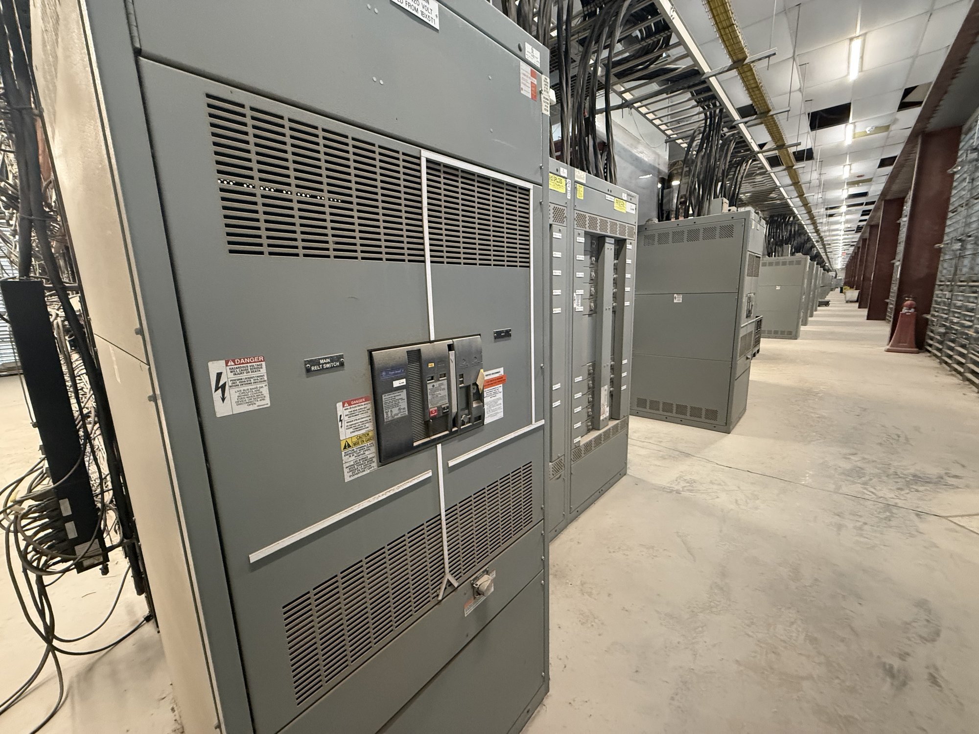
Clarify whether the generator connection is a termination section within a switchboard or part of a larger lineup with transfer, distribution, or paralleling equipment. A dedicated section can organize incoming conductors and provide space for specified switching and protection devices, but it does not by itself establish transfer logic, prevent unintended paralleling, or authorize export to the utility. Those functions depend on the complete system design and applicable review.
Specify source and conductor interfaces
Provide the generator’s electrical data and the intended connection details: voltage, phase, frequency, full-load current or kW and power factor, available fault current, grounding arrangement, and whether the neutral is switched. Identify conductor material, quantity, size, insulation type, entry direction, routing, and lug requirements when known. Also note generator breaker details and any limits from the generator package. These inputs help establish section dimensions, termination space, bus connections, and device interfaces.
Confirm the physical relationship between the generator and switchgear. Share equipment-room constraints, lineup orientation, cable approach, conduit locations, access clearances, and the planned route from the generator terminals. Long or multiple parallel conductors can affect bending space and termination layout. If information is still preliminary, label assumptions clearly rather than treating them as final; the approved drawings should resolve outstanding dimensions and interfaces before fabrication.
Coordinate switching and protection
The switching arrangement should reflect the one-line diagram and sequence of operation. Identify whether the generator connects through a circuit breaker, a transfer arrangement, or a paralleling scheme, and state which devices are supplied in the switchgear scope. Describe the normal and alternate source paths, required isolation points, and whether operators need local control or status indication. Where automatic transfer or synchronizing is involved, define the control and communication boundaries with the generator controls and other system equipment.
Protection settings and functions require project-specific engineering. The design team should establish short-circuit and coordination requirements, grounding-fault approach, generator protection, and any directional, synchronism-check, or anti-islanding functions relevant to the operating mode. Utility interconnection requirements and authority review may apply when sources can operate in parallel or export power. UL 891 applies to switchboard assemblies; it is not a blanket listing for medium- or high-voltage switchgear, and the applicable equipment type and standards must be determined for the project.
Resolve lineup and operating details
A useful specification addresses more than the breaker or cable lugs. Confirm the lineup’s bus rating and configuration, enclosure and service conditions, metering needs, control power source, instrument transformers if required, indication, and any provisions for future generator capacity. State whether the connection must accommodate a temporary generator, permanently installed unit, or either, and whether external docking hardware or interlocked access is part of the design. Each feature affects layout, wiring, and scope.
Review service and maintenance access with qualified personnel as the layout develops. The connection section must coordinate with adjacent sections, barriers, cable supports, and the room’s working space. Do not assume a nominal section width or a particular device arrangement will fit the project. The manufacturer’s proposed configuration should be checked against the engineered drawings, generator documentation, installation conditions, and applicable authority requirements before release.
Prepare a complete quote package
For a useful quotation, share the latest one-line diagram, equipment schedule, generator submittal, preliminary fault-current information, and written sequence of operation. Include the requested voltage and bus data, breaker requirements, termination details, enclosure conditions, control interfaces, metering, and any required drawing or testing scope. Identify the project location in Georgia, delivery point, site access constraints, requested ship window, and who will approve submittals. If a design item is undecided, identify the responsible engineer and the date it is expected to be resolved.
The quote and submittal process should make assumptions visible: what is included in the switchgear assembly, what is furnished by the generator or controls contractor, and what remains by others. Confirm final dimensions, conductor entry, device ratings, control wiring, and interface points through drawing review. Availability, configuration, and schedule are confirmed for each order; Georgia delivery planning can then be coordinated to the project’s receiving and installation sequence without assuming a fixed transit or lead time.
Carry the design through handoff
Before approving production drawings, have the electrical engineer verify the source arrangement, protection basis, interconnection requirements, and equipment interfaces. The contractor should confirm field dimensions, routing, access, and conduit locations, while the facilities team should validate operating and maintenance needs. Purchasing managers can use the same approved scope to compare quotations and track open decisions, reducing the risk of mismatched generator, controls, and switchgear responsibilities.
For your quote request, send the one-line diagram, generator data, conductor and entry requirements, switching sequence, protection responsibilities, site constraints, and Georgia delivery location. Mark each item as confirmed or pending and identify the person responsible for resolving it. That focused package gives the manufacturer a practical basis to develop a dedicated connection section around the project design, then carry agreed details into submittal and delivery planning.