Define the transfer arrangement
Start by documenting what the transfer switch serves and how normal and alternate sources reach it. Identify source types, nominal system voltage, phase and wire configuration, grounding approach, available fault-current information and the intended load. Clarify whether the switch is a standalone device, part of a switchboard lineup or connected between separate assemblies. These details determine which physical and electrical boundaries the design must preserve.
Specify the transfer function rather than assuming a standard arrangement. A project may require open-transition operation, closed-transition capability, delayed transition or another sequence, but suitability depends on the application and equipment. State whether the load is a single branch, a group of feeders or a downstream distribution assembly. The engineer of record and equipment manufacturers should resolve operating sequence, source coordination and applicable project requirements before the configuration is finalized.
Coordinate upstream source connections
For each source, identify the upstream assembly and the intended point of connection. Share one-line diagrams, conductor or bus connection preferences, service and feeder details, and any physical separation requirements. A transfer switch may receive normal power from a service switchboard and alternate power from a generator distribution section, but the actual topology varies. Confirm which party furnishes and terminates each connection, including any transition section or external raceway.
Upstream overcurrent protection and transfer equipment must be coordinated as a system. Provide available fault-current data, protective-device information and the project’s selective-coordination or study requirements when applicable. Do not assume that the transfer switch’s withstand capability, upstream device settings or source grounding arrangement can be inferred from a panel schedule. Engineering review should establish the required device relationships and confirm that the proposed assembly interfaces match the approved design.
Plan the load-side interface
On the load side, define whether the transfer switch feeds a dedicated distribution section, a main device, multiple outgoing feeders or a connection to an existing assembly. Identify feeder quantities, conductor sizes when established, termination type, cable entry direction and any bus connection requirements. Provide load schedules and distinguish essential, emergency or other project-defined loads where those categories affect grouping and operation.
Physical layout matters as much as the one-line diagram. Confirm lineup dimensions and orientation, access and working-space constraints, conduit or cable approach, equipment room restrictions, and whether the switch needs to be serviceable without disturbing adjacent sections. Note shipping splits, lifting or rigging limits, and the route from receiving point to final location. Final clearances and installation conditions require review by the project’s qualified electrical professionals and authority having jurisdiction.
Specify controls and operating interfaces
Describe how the transfer switch is expected to detect source conditions and initiate transfer. Identify generator start contacts, remote status points, alarms, communications expectations and any interface with building controls or an emergency-power system. State preferred terminal or wiring handoff boundaries where known, and provide control voltage and sequence information from the project documents. Confirm which controls are integral to the switch and which are supplied or wired by others.
Discuss test and maintenance functions early. The specification may call for a test connection, bypass-isolation arrangement, manual operation, source indication or a particular means of maintaining the load during service. These options affect enclosure space, access, wiring and the operational sequence; they should not be added as assumptions late in fabrication. The responsible engineer should verify that the selected features suit the facility’s operating procedures and required system performance.
Resolve enclosure and assembly boundaries
A custom-built configuration must show where the transfer-switch section ends and adjacent switchgear begins. Confirm enclosure type and environmental conditions, lineup arrangement, barriers, access doors, cable compartments and any separation requested by the project. If the switchboard assembly is specified to UL 891, define the intended assembly scope and review the complete configuration against that standard. UL 891 applies to switchboards; it is not a blanket listing for medium- or high-voltage switchgear.
Share drawings and responsibility boundaries before release. Identify who supplies the transfer device, who provides the surrounding assembly, who performs field interconnection and who verifies control wiring. Where equipment from different manufacturers or separately furnished sections must connect, document dimensions, termination details and interface tolerances for review. Final design, ratings and compliance require appropriate engineering evaluation and acceptance by the authority having jurisdiction.
Prepare a complete Georgia project handoff
For a quotation, provide the latest one-line and relevant elevations, source and load information, transfer sequence, protection data, control requirements, enclosure constraints, requested accessories and the desired division of supply and field work. Include project location in Georgia, receiving conditions, delivery access and any milestone dates. Note unresolved items explicitly so they can be addressed during design review rather than treated as confirmed requirements.
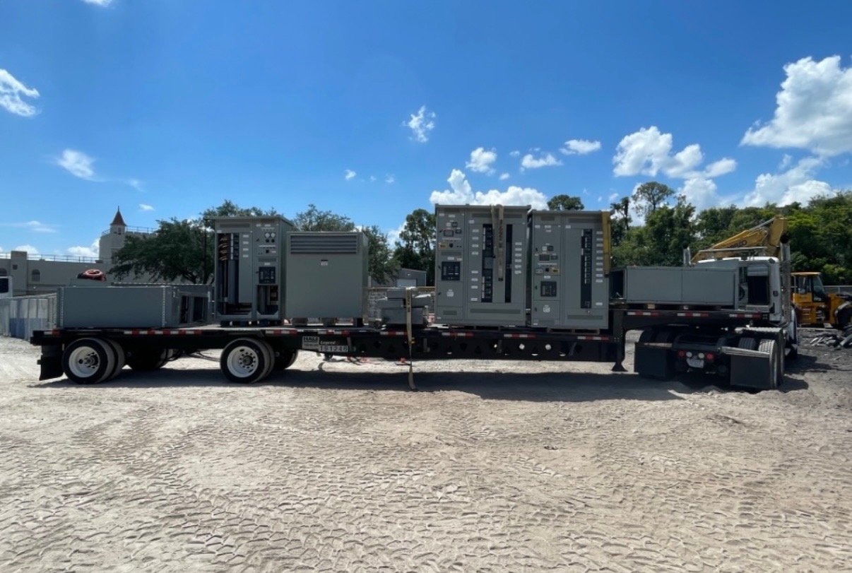
Georgia delivery can be coordinated with the project’s receiving and installation plan, while nationwide shipping supports projects with broader supply needs. Share the destination, unloading arrangements, site-readiness assumptions and required delivery window; exact scope, availability and timeline are confirmed for each order. Before release, align the approved drawings, connection schedule, control handoff and delivery plan among the engineer, contractor, facility team and purchasing group.