Start with the electrical growth case
Before specifying an expansion, distinguish present demand from the capacity the site expects to need at each growth phase. Share the current one-line diagram, connected and measured loads where available, planned IT load additions, and the expected timing of new halls or buildings. These inputs help the project engineer assess whether existing distribution can support staged additions or whether the main service and upstream equipment also need changes.
Ask which constraints govern the expansion: service capacity, transformer or generator capability, bus rating, feeder space, fault-current limits, or the physical route to the new load. A switchboard section cannot create capacity that upstream equipment does not provide. Have the responsible electrical engineer verify system coordination, available fault current, grounding, and applicable design requirements before equipment ratings or tie arrangements are finalized.
Specify bus capacity and usable space
Bus capacity should reflect the engineered load case and operating arrangement, not a simple estimate based on the number of planned racks. Clarify the continuous load assumptions, diversity, redundancy strategy, and whether normal and alternate sources can operate in parallel or transfer between one another. Confirm the required bus rating, neutral treatment, and short-circuit withstand or interrupting requirements with the design team; these depend on the complete system and cannot be inferred from facility size.
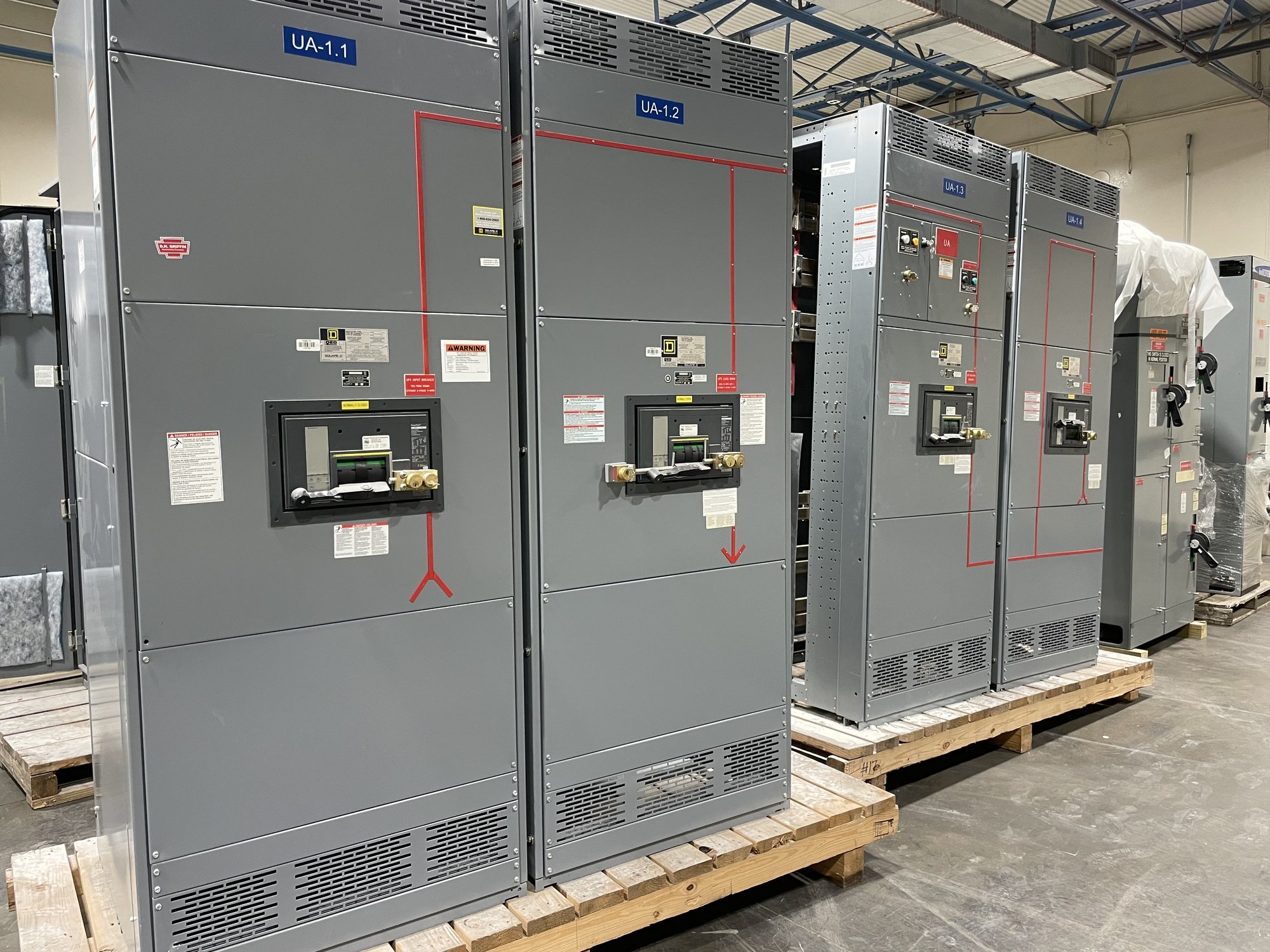
Reserve space deliberately for future distribution sections, feeder devices, cable entry, and access needed for installation and maintenance. Ask whether future sections are intended to be installed adjacent to the initial lineup, in a separate room, or as a later replacement. The answer affects section arrangement, shipping splits, bus connections, room dimensions, and the interfaces that must be documented now. A reserved footprint alone does not ensure that future equipment will connect to the original assembly.
Design around construction phases
A phased plan should identify what is installed in each stage, which loads each stage serves, and how the temporary and permanent electrical configurations will be reviewed. Provide the sequence for room turnover, equipment delivery, cable installation, commissioning, and load transfer. The switchboard scope can then be evaluated against practical boundaries such as shipping sections, access paths, available working space, and the point at which a future section can be connected.
Decide early whether the initial order should include only the first phase or a larger assembly with provisions for planned growth. Future sections may require matching bus geometry, device arrangements, cable spaces, and control interfaces, so define the intended extension point and retain the approved drawings and equipment data. Confirm availability and schedule for each phase when ordering; exact configuration, components, and timing are established for the specific project.
Treat outage limits as design inputs
For an operating data center, the allowable outage may be narrower than the construction window. Document which buses and loads must remain energized, what redundancy is available, and whether a planned transfer can occur during maintenance. The facility operator and qualified electrical professionals should determine switching steps, temporary power needs, and commissioning boundaries. Equipment selection by itself does not establish an acceptable outage plan.
Ask the design team to identify every interface that could require interruption, including incoming connections, bus ties, feeder terminations, control wiring, and protection changes. If new sections are intended to minimize disruption, verify that the proposed arrangement actually supports the planned sequence and that the required isolation and testing can be performed. Review the final method and work controls with the responsible parties before construction or energization.
Coordinate scope, drawings and procurement
For a manufacturer quote, provide the one-line diagram, equipment schedule, bus and device requirements, enclosure and room constraints, cable-entry preferences, and desired future-section arrangement. Include the project phase, target delivery location in Georgia, access restrictions, and the dates tied to construction milestones. Identify whether the requested assembly is a UL 891 switchboard and define the required scope; UL 891 applies to switchboards and does not serve as a blanket listing for medium- or high-voltage switchgear.
Before release, align the approved drawings with the electrical engineer, contractor, facility team, and procurement group. Check section dimensions, shipping splits, connection details, device functions, control interfaces, and any field work expected at each phase. American-made components and custom-built configurations may be considered within the requested scope, subject to confirmation. Georgia delivery can be coordinated with the project sequence, but route, shipment timing, and receiving requirements should be confirmed for the order.
Make the expansion handoff actionable
A useful handoff gives the next project team more than a placeholder on a floor plan. Retain the current and future one-line diagrams, approved equipment drawings, bus and device data, interface notes, and the assumptions behind the load forecast. Record which capacities are installed, which are reserved, and what upstream work remains before a future section can be added. This reduces the risk that a later phase is designed around an outdated or incomplete understanding of the system.
For a quote, send the growth schedule, outage constraints, available drawings, desired future-section boundaries, and Georgia delivery point together. Ask the engineering team to resolve rating and system questions, then confirm equipment scope and timing against the construction plan before purchase. This gives procurement a defined first phase and gives facilities staff a traceable basis for evaluating the next capacity addition.