Define the operating sequence
Start by documenting how the facility is expected to respond to a utility disturbance. The sequence may call for multiple generator sets to start, synchronize to a common bus, and assume load in stages, but the details depend on the site’s operating philosophy. Clarify whether generators run in parallel only during an outage, also support planned testing, or participate in another approved operating mode.
Identify which loads transfer first, which can wait, and which must remain isolated until capacity is available. Include cooling, pumps, controls, UPS input, and other major loads in the discussion, while distinguishing essential loads from deferred or shed loads. These decisions shape the paralleling arrangement and control interfaces; they should be established with the project’s electrical engineer and generator-system designer.
Coordinate synchronization and protection
A paralleling system must coordinate generator voltage, frequency, phase, breaker operation, and bus conditions according to the selected controls and operating sequence. Define how synchronizing is initiated, what permissives are required, how failed starts or unsuccessful synchronization are handled, and what happens if one generator becomes unavailable. Control logic and protective-device functions must be reviewed together rather than specified as unrelated components.
For quotation and design development, provide available generator data, intended bus arrangement, system voltage, fault-current information, grounding approach, and preliminary protection requirements. Identify who supplies and configures the generator controls, protective relays, metering, and communications interfaces. Final settings and coordination require project-specific engineering and review by the appropriate authorities; UL 891 applies to switchboard assemblies, not as a blanket certification for every component or system.
Plan staged loading and load shedding
Staged loading limits the amount of demand added to the generator bus at one time. The sequence should account for generator capacity, motor starting characteristics, UPS behavior, cooling-system response, and the time required for each load group to stabilize. A practical schedule identifies the conditions that permit each stage, the priority of each group, and the response when available generation falls below the planned level.
Discuss whether automatic load shedding is required and which loads may be dropped first. Consider recovery after a shed event, including whether loads reconnect automatically, require operator action, or wait for additional generation. Share the load list, expected demand by operating mode, major step loads, and any known restrictions early. These inputs help the project team assess bus sections, feeder organization, control points, and the sequence interfaces without assuming a particular facility design.
Shape the switchboard and distribution
The generator bus and downstream distribution need to reflect both the one-line diagram and the intended maintenance strategy. Engineering teams should resolve generator breaker locations, bus ties, normal and emergency sources, feeder destinations, metering, and separation between load groups. Physical constraints also matter: available electrical-room space, cable entry direction, access for inspection, and the route from generator equipment to the distribution lineup can affect the build configuration.
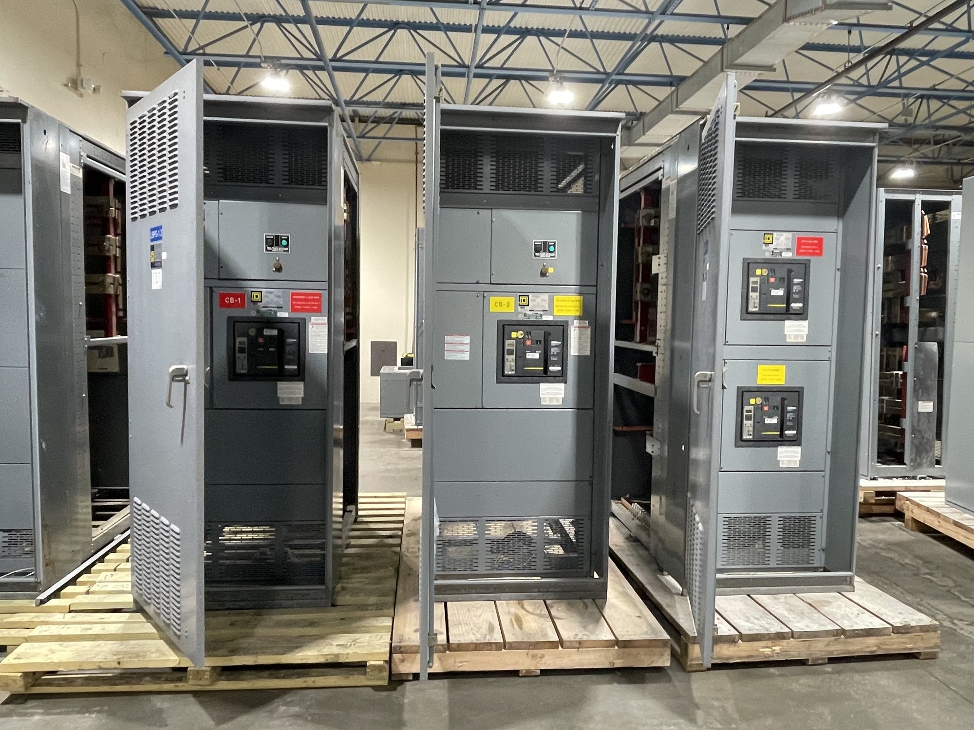
When specifying a custom-built switchboard assembly, identify the required sections, device functions, bus arrangement, connection points, and project documentation. Confirm the intended assembly standard and scope rather than assuming every part of a power system has the same certification status. The final design, ratings, protective coordination, and installation details must be established and reviewed for the specific project.
Resolve interfaces before procurement
Generator paralleling projects involve equipment and control boundaries that should be explicit in the purchase documents. Establish responsibility for generator controls, switchgear controls, relay programming, network communications, remote annunciation, and factory or site testing. Define the signals exchanged between systems, the communication method where applicable, and the documents needed to verify those interfaces before equipment is released for manufacture.
For a useful quote, share the one-line diagram, equipment schedule, generator count and data, load-sequencing narrative, preliminary room dimensions, required options, and target project dates. Note any specified component preferences and whether drawings, submittals, or witness testing are part of the requested scope. Availability, configuration, and schedule are confirmed for each order, so procurement should align the requested delivery window with design approvals and site readiness.
Coordinate Georgia delivery and handoff
For a Georgia project, delivery planning should connect the equipment schedule to the site’s construction sequence. Confirm the receiving location, unloading and access constraints, storage conditions, installation window, and whether the lineup must arrive in planned sections. Nationwide shipping is available, with delivery details coordinated for the order; the project team should allow for site-specific transport and handling requirements.
Before release, align approved drawings, final connection details, control interface documents, and the delivery plan with the engineer, contractor, generator supplier, and facilities team. Provide the intended operating sequence and load priorities alongside the quote request, then identify unresolved protection or control decisions. This gives the equipment scope a clear basis and helps the project team carry generator coordination through procurement, installation planning, and commissioning.