Set the recovery priorities
Start with the consequences of losing each load, not just its nameplate demand. Identify refrigeration compressors, evaporator fans, condenser equipment, pumps, defrost controls, temperature monitoring, alarms and communications. Separate equipment that must remain available from loads that can wait, cycle or remain off during an outage. Product type, room temperature, door activity and the facility’s operating procedures all affect those priorities.
A practical load schedule should state what must run immediately, what may start after a delay and what can be shed if the backup source is constrained. Include the conditions for restoring deferred loads, such as stable source voltage or an operator action. This gives the engineer a usable basis for sequencing and gives procurement a defined scope instead of an assumption that every connected load needs simultaneous backup.
Map the source and transfer arrangement
Document the normal service, proposed generator or temporary-power connection, transfer equipment and distribution sections involved. Clarify whether backup power serves the full facility, selected refrigeration panels or a dedicated emergency distribution section. The one-line diagram should show source boundaries, tie points, protective devices, metering needs and any interlocks needed to prevent unintended source paralleling or backfeed.
Transfer behavior is a key design decision. Ask whether refrigeration loads are expected to ride through a brief interruption, restart in stages after transfer, or require a specific return-to-normal sequence. Generator capability, motor starting, available fault current and control-system behavior need engineering review together. Do not assume a transfer scheme or source rating from connected load totals alone; operating conditions and equipment data matter.
Account for motor starts and control power
Compressors and other motors can draw substantially more current during starting than while running. Gather motor horsepower, voltage, full-load current, starting method, acceleration time where known and manufacturer data for variable-frequency drives or soft starters. Also record which motors may start together and which controls inhibit or sequence them. These details help evaluate generator loading, voltage dip and the distribution equipment required for the intended operating sequence.
Keep control power, alarms and temperature monitoring in the priority discussion. A compressor may be available while its controls, network connection or sensor circuit is not, leaving operators without reliable status or safe restart logic. Identify control voltage sources, required ride-through, remote monitoring dependencies and any loads that need uninterruptible power separately from generator-backed distribution. Final settings and operating sequences belong with the responsible electrical and controls engineers.
Specify the assembly around the facility
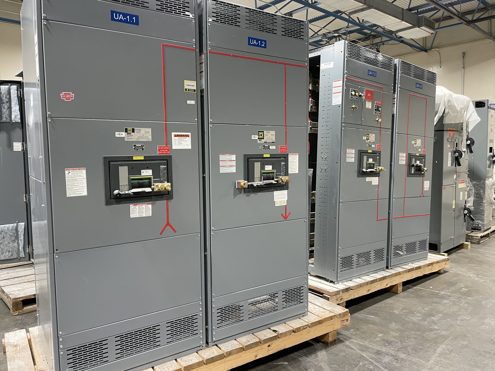
For a new switchboard assembly, provide the system voltage, phase and wire configuration, service or feeder role, available fault-current information, main and branch device requirements, enclosure conditions and connection details. Note whether the equipment is indoors or exposed to washdown, condensation, corrosive conditions or temperature extremes. UL 891 applies to switchboard assemblies; it should not be treated as a blanket listing for other classes of switchgear or for an entire backup system.
Custom configuration can address section arrangement, incoming-source connections, feeder distribution, metering and control interfaces when included in the engineered scope. Confirm working space, cable entry direction, conduit locations, shipping dimensions, lifting access and the route into the electrical room before release. The final design, protective-device coordination, grounding, installation and acceptance remain subject to qualified engineering and applicable authority review.
Prepare a quote-ready project package
For a useful quotation, share the latest one-line diagram, load list, source and generator data, motor schedules, control sequence, fault-current study if available, and the required transfer concept. State which loads are critical, deferred or shed, and explain any operating limits that affect backup duration or restart. Include requested options, project milestones, drawing requirements and the person responsible for resolving technical questions.
Procurement should also identify the delivery destination in Georgia, receiving hours, unloading capability, site access restrictions and whether the assembly must arrive in coordinated sections. Confirm the required submittal and approval sequence, plus dependencies on generator, transfer equipment, field wiring or other vendors. Exact scope, component availability and schedule are confirmed for each order; early disclosure of interfaces helps avoid late changes.
Coordinate delivery and commissioning handoff
Before equipment release, align the approved drawings with the facility’s final feeder assignments, source interfaces and operating sequence. Resolve who supplies conductors, controls, interconnection hardware and field terminations, and who verifies protective-device settings. For a temporary-power plan, document connection points and the process for connecting or removing the source. Work on installation and energization should be performed by qualified personnel under the project’s approved procedures.
Georgia delivery can be coordinated to the project’s receiving location and schedule, with shipping details confirmed for the order rather than assumed. Give the manufacturer the delivery window, access constraints, unloading plan and any phased shipment needs. A strong handoff includes approved drawings, equipment documentation, final load priorities and clear interface responsibilities, so the facility team can connect the new distribution assembly to the engineered backup plan.