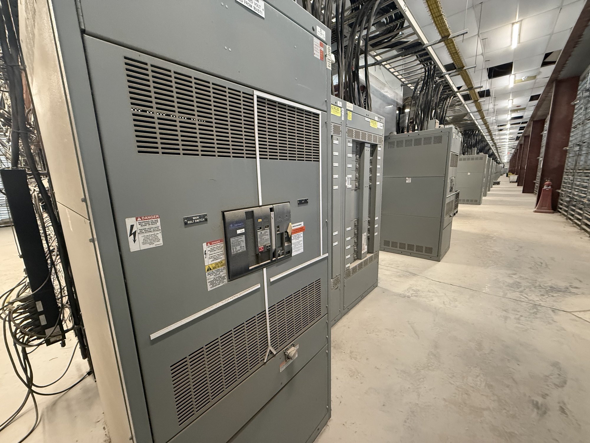
What arc-resistant construction is intended to do
An internal arc can release intense heat, pressure, and hot gases inside an electrical assembly. Arc-resistant construction uses features such as reinforced enclosures, secured covers, latches, and controlled relief paths to limit hazards to people in defined areas under specified test conditions. Its purpose is risk reduction during a particular internal-arc event, not prevention of the event itself.
This construction does not replace equipment selection, protective-device coordination, safe work practices, or site-specific hazard analysis. It does not make energized work inherently safe or eliminate risks from every fault, operating condition, or maintenance task. The project engineer and facility safety team should determine how the equipment fits the broader electrical safety plan.
Treat the test as a configuration boundary
Arc-resistance claims apply to tested equipment arrangements, not to a general product family or a single enclosure feature. Relevant details can include the assembly’s dimensions, compartments, doors and covers, bus arrangement, protective devices, access sides, and the position of the equipment during testing. The specified rating and accessible sides must match the manufacturer’s documented test scope.
Ask which exact configuration and access conditions the test documentation covers, and identify any exclusions or required installation conditions. A change in lineup arrangement, end section, compartment, or field modification may affect whether the documented result applies. Do not assume that a tested section makes an adjacent enclosure, connected equipment, or the surrounding room arc-resistant.
Plan the pressure and exhaust path early
Arc-resistant assemblies may direct pressure and gases through a plenum, duct, or other designated exhaust route. That route needs a clear destination and must be coordinated with room layout, overhead obstructions, walls, ceilings, ventilation, and nearby equipment. The path cannot be treated as spare space for later piping, cable tray, or building services.
During design, establish the required equipment clearances and the full exhaust route from the assembly to its discharge point. Confirm who is responsible for structural openings, duct supports, weather protection, and coordination with building trades. The manufacturer can define assembly interfaces and requirements for the offered configuration; the project team must verify that the building arrangement accommodates them.
Choose access and operating arrangements
Specify which sides require arc-resistant protection based on the equipment location and the areas personnel may occupy. Front-only access and arrangements intended for access on additional sides are not interchangeable assumptions. Include the planned lineup orientation, adjacent walls, working areas, and any rear access needed for inspection or maintenance when requesting a configuration.
Consider how operators will interact with the equipment, including normal switching, racking where applicable, and access to controls. Arc-resistant enclosure features do not determine the site’s operating procedures or establish that a task can be performed while energized. The facility’s qualified electrical personnel and engineering team should review equipment access, procedures, and the applicable risk controls.
Resolve equipment scope and interfaces
Arc-resistant construction is available only within defined equipment designs and ratings; it should not be assumed for every voltage class, lineup, or arrangement. For low-voltage switchboards, UL 891 is a switchboard standard and does not establish arc-resistant performance by itself. Any arc-resistant claim needs separate, configuration-specific supporting documentation. Medium- or high-voltage equipment requires its own applicable standards and evidence.
A custom-built assembly still has practical limits. Bus ratings, fault-duty requirements, protective-device selection, metering, incoming and outgoing connections, enclosure dimensions, and available space all affect the design. Provide one-line diagrams and project specifications where available, and identify requested options clearly. Engineering review must resolve compatibility and confirm the final scope rather than relying on a generic description.
Prepare a quote and project handoff
For a useful quote, share the system voltage, required continuous and fault ratings, lineup length or section count, access-side needs, one-line diagram, protective-device requirements, and project schedule. Include room drawings or dimensions showing the proposed exhaust route, discharge location, overhead constraints, and adjacent equipment. State whether the project has a defined arc-resistant specification or needs configuration options reviewed.
For Georgia delivery, coordinate the ship-to site, receiving access, unloading plan, and required delivery window with the project schedule. Confirm the proposed assembly scope, documented test boundaries, exhaust interfaces, submittals, and installation responsibilities before release for production. Provide the electrical and room-layout documents with your quote request so configuration, availability, and timing can be confirmed for the specific order.