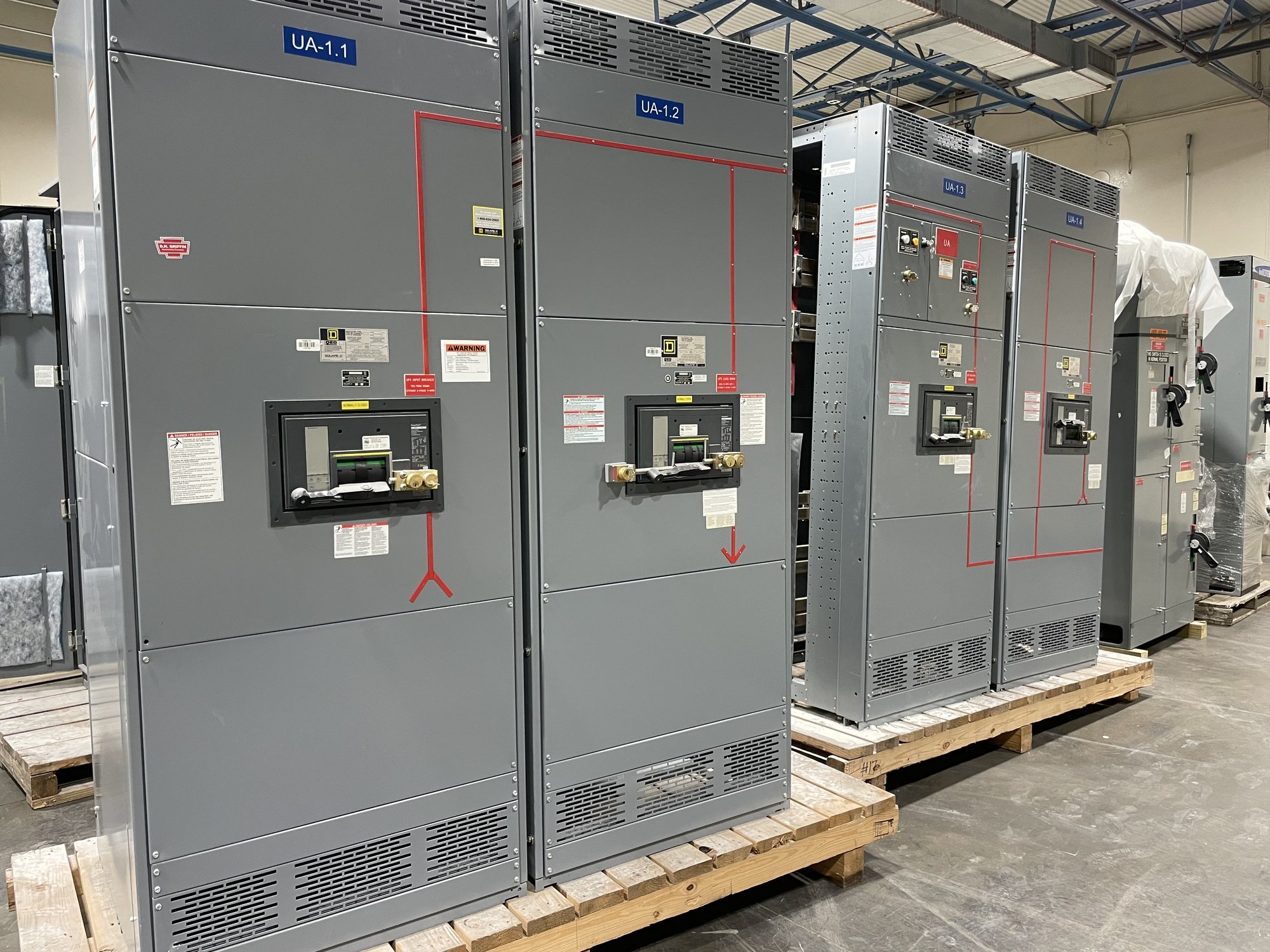
Start with the applicable requirement
The first decision is whether an arc-energy reduction provision applies to the equipment and overcurrent protective device in question. Applicable rules can vary with device type, ampere rating, equipment configuration and the edition of the adopted electrical code. A requirement for one switchboard main or feeder does not automatically establish the requirement for every device in the lineup.
Confirm the code edition and any local amendments with the authority having jurisdiction and the project engineer. Then identify which devices fall within the provision under review. This keeps the specification tied to the actual installation rather than an assumed threshold or a general statement that all switchgear must include one particular method.
Identify the device and its operating details
Document whether the protective device is a circuit breaker or fuse, its manufacturer and model if selected, its continuous-current rating, trip unit or fuse class, and its role as a main or feeder. For breakers, include available trip functions and control features. The method that can be implemented depends on the device’s capabilities and the way it is connected to the system.
Provide system voltage, available fault-current information, transformer and source data, and relevant conductor lengths when available. These inputs help the engineer evaluate protection coordination and incident-energy implications. A device rating alone does not establish clearing time or the suitability of a reduction method; those conclusions depend on the complete system and settings.
Compare methods without assuming equivalence
Depending on the applicable provision and device, potential approaches may include an instantaneous trip function, a maintenance-mode setting that temporarily changes protection behavior, an energy-reducing maintenance switch, or zone-selective interlocking. A current-limiting fuse may be relevant in some designs. These options are not interchangeable by default, and not every device supports every approach.
Ask the engineer to identify the selected method for each applicable device and explain how it operates, how it is activated, and how normal protection coordination is preserved. If a maintenance mode is proposed, clarify its indication, control location, intended use and return-to-normal procedure. If interlocking or a trip-unit function is proposed, confirm compatible devices, wiring and settings.
Coordinate protection, labeling and access
Reducing clearing time for maintenance can affect coordination with downstream devices or alter normal operating behavior. Review the proposed settings against the coordination study, fault-current calculations and arc-flash analysis as applicable. The engineer should determine whether the selected approach achieves the project objective while addressing selective operation and the equipment’s operating constraints.
Specify required controls, indicators, labels, wiring diagrams and test documentation rather than relying on a generic note. The project team should define who verifies settings and functional operation, and how workers are instructed to use any maintenance feature. Only qualified personnel should install, inspect, operate or service electrical equipment under the applicable procedures.
Make the scope quote-ready
For a manufacturer quote, share the one-line diagram, equipment schedule, system voltage, main and feeder device types and ratings, available fault-current data, selected code edition, and the engineer’s specified reduction method. Include enclosure and lineup requirements, incoming and outgoing arrangements, control-power needs, and any required labels or documentation. If the method is not yet selected, say so and identify who will resolve it.
Also note whether the design calls for a UL 891 switchboard assembly. UL 891 applies to switchboards; it is not a blanket listing for medium- or high-voltage switchgear. Confirm the requested assembly scope and applicable documentation for the specific order. Exact configuration, component availability and production timeline are confirmed during order review, not inferred from a general specification.
Plan Georgia delivery and project handoff
For Georgia projects, provide the delivery location, requested site date, receiving restrictions, unloading arrangements and the party coordinating site access. Nationwide shipping can support delivery to a Georgia project, but routing and timing depend on the order scope and are confirmed for each order. Align the delivery plan with installation sequencing and the availability of qualified electrical personnel.
Before releasing the purchase specification, ask the engineer to confirm the governing code edition, the devices covered, the chosen method for each device, and the related settings, controls and documentation. Send those decisions with the one-line and equipment schedule for a new switchboard quote. Clear responsibility at handoff helps purchasing, manufacturing and field teams work from the same defined scope.