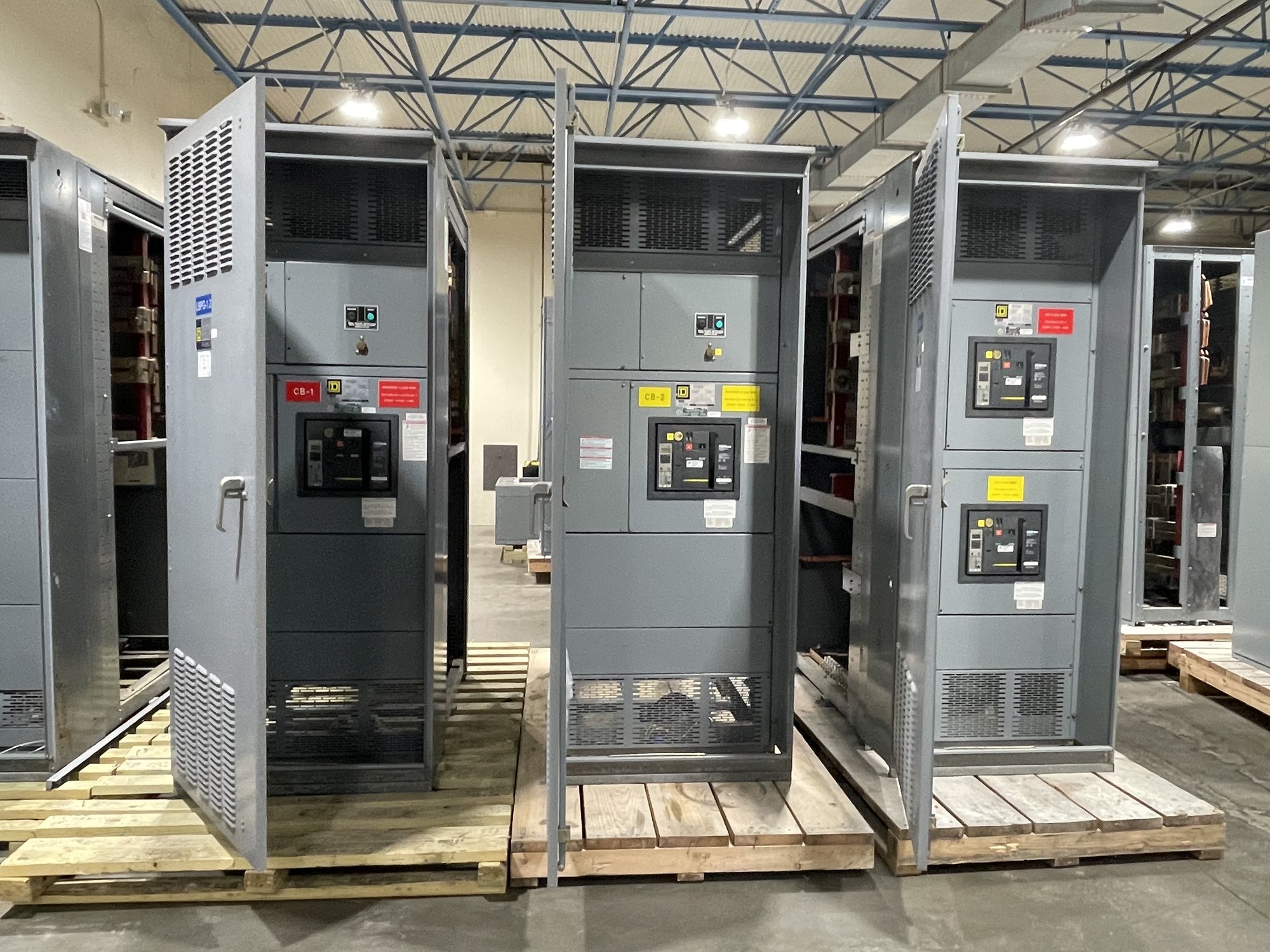
Start with the application and design basis
Identify the equipment type and system requirements before comparing aluminum with copper. Share the one-line diagram, nominal system voltage, available fault-current information, required continuous current, grounding arrangement, and service conditions. These inputs let the manufacturer review the proposed bus within the complete assembly rather than treating conductor material as an isolated substitution.
Clarify whether the project calls for a switchboard assembly or another class of switchgear. UL 891 applies to switchboards; it is not a blanket listing for medium- or high-voltage switchgear. Specify the required standard, documentation, and approval path for the actual equipment, then have qualified engineering personnel and the authority having jurisdiction review the design and application.
Account for dimensions and enclosure space
Aluminum and copper do not have identical electrical or mechanical properties. A design using aluminum may require different conductor cross-section or arrangement to meet the specified current and temperature limits. That can affect bus spacing, supports, barriers, compartment layout, cable bending space, and enclosure dimensions. Do not assume a copper layout can accept aluminum bus without engineering review.
For retrofit or tight-room projects, provide available width, depth, height, access clearances, cable entry direction, and any fixed interfaces. Include the dimensions and locations of existing conduits, bus duct, or equipment terminations where applicable. These constraints help determine whether the proposed assembly and conductor geometry can fit while preserving the required working and maintenance access.
Define connections and termination details
List every incoming, outgoing, and inter-section connection, including conductor material and size, number of conductors per phase, lug or pad requirements, and cable or bus-duct entry orientation. State whether the bus connects to transformers, generators, service conductors, or other equipment, and provide the mating interface information. A vague description such as “top entry” may not resolve actual landing space or connector needs.
Connection hardware and contact surfaces must be compatible with the specified conductors and the engineered assembly. Identify any transition connections between aluminum and copper, and describe the equipment or field conductors that will meet each termination. Confirm these details in approved drawings before fabrication so the field crew can plan routing, lug selection, access, and installation under the project’s applicable procedures.
Specify joint preparation and assembly controls
Aluminum joints require deliberate preparation and assembly practices because surface condition and connection method affect contact quality. The design and manufacturer’s instructions should define the approved joint materials, surface preparation, hardware, and tightening method for the supplied equipment. Do not rely on a generic field assumption or substitute a compound, washer, or fastener without confirmation for the specific connection.
For procurement, ask what joint locations are factory assembled and which connections require field completion. Request applicable assembly instructions and torque values with the equipment documentation, and make clear who is responsible for field connections. Qualified personnel should follow the approved instructions and project procedures; the manufacturer should confirm any proposed change before it is made.
Verify ratings and supporting documentation
The bus material alone does not establish the assembly’s current rating, short-circuit capability, temperature performance, or suitability for a particular environment. Verify the ratings for the complete configuration, including bus arrangement, supports, joints, protective devices, enclosure, and any transitions. Provide the required system conditions and identify project specifications that govern these checks rather than inferring ratings from a similar-looking lineup.
For a UL 891 switchboard, request documentation that identifies the assembly scope and applicable rating information. Confirm how the proposed aluminum bus configuration is represented in the drawings and submittal package. Any change in bus size, connection arrangement, enclosure, or protective-device selection should be reviewed for its effect on the assembly and its documented ratings before release.
Prepare the quote and Georgia delivery handoff
For a useful quote, send the one-line diagram, equipment type, electrical requirements, preferred bus material, available space, conductor and termination data, entry direction, connection interfaces, and project specification. Include required submittals, drawing review milestones, site constraints, and the requested delivery location in Georgia. Flag any unresolved design choices so they can be identified before the configuration is finalized.
Ask the manufacturer to confirm the proposed dimensions, joint scope, rating documentation, availability, and expected schedule for the specific order. Coordinate shipment with the site’s receiving hours, unloading capability, access route, and installation sequence; shipping arrangements and timing are confirmed for each order. Before release, reconcile the approved drawings with field interfaces and assign qualified personnel to review installation requirements.