Verification is a work-control step
A de-energized indication, open breaker, or control-system status is not, by itself, verification that conductors at the intended work point are free of voltage. Qualified personnel establish the electrically safe work condition under the applicable procedures, identify all possible sources, isolate them, address stored energy, and verify at the point of work. The sequence and responsibilities belong in the site’s electrical safety program and task planning.
The required checks depend on the circuit and equipment. Personnel need to consider normal and alternate feeds, tie breakers, generators, UPS systems, control power, backfeed, induced voltage, and energy stored in capacitors or other components. Equipment drawings and labels should help identify boundaries and sources, but they do not replace field identification, isolation, or testing by qualified personnel.
Use an instrument suited to the circuit
The test instrument must be appropriate for the expected voltage, measurement category, environment, and access conditions. Qualified personnel select and inspect it under site procedures, including test leads and accessories. A noncontact detector or remote indication may support an assessment, but neither alone establishes absence of voltage at the work location.
A commonly used verification sequence is to prove the tester on a known source or proving unit, test each relevant phase-to-phase and phase-to-ground combination at the point of work, then prove the tester again. Site rules, equipment configuration, and applicable requirements govern the exact method. If readings are unexpected, unstable, or inconsistent, personnel stop and resolve the condition before proceeding.
Specify access and documentation
When specifying new switchgear or a UL 891 switchboard assembly, ask how qualified personnel will reach the intended test points after isolation. Discuss whether access can be provided without unnecessary exposure to adjacent energized parts, how barriers and compartment boundaries affect testing, and whether test points, terminal locations, or drawings need clear identification. The appropriate arrangement depends on the design and must be reviewed by the responsible engineer.
Procurement documents can request current one-line diagrams, control schematics, equipment labels, terminal information, and instructions relevant to isolation and testing. Confirm the document formats, drawing revisions, and handoff timing required for commissioning and maintenance planning. UL 891 applies to switchboard assemblies; it does not establish a blanket listing for medium- or high-voltage switchgear or substitute for project-specific engineering review.
Resolve project-specific constraints early
A retrofit or constrained electrical room can limit test access, instrument placement, door swing, working space, and the ability to isolate one section while others remain in service. Share room layouts, existing one-lines, service conditions, known source configurations, and the planned work boundary during design. Do not assume that a feature shown on a preliminary drawing will provide adequate access in the installed arrangement.
For a quote, provide the equipment type, system voltage and configuration, main and tie arrangements, incoming and alternate sources, required sections, installation setting, and desired documentation. Identify any site-specific testing or labeling requirements and who will approve the final design. Exact scope, component availability, and schedule are confirmed for each order; engineering review is needed where the requested arrangement affects access or operating procedures.
Coordinate delivery and the field handoff
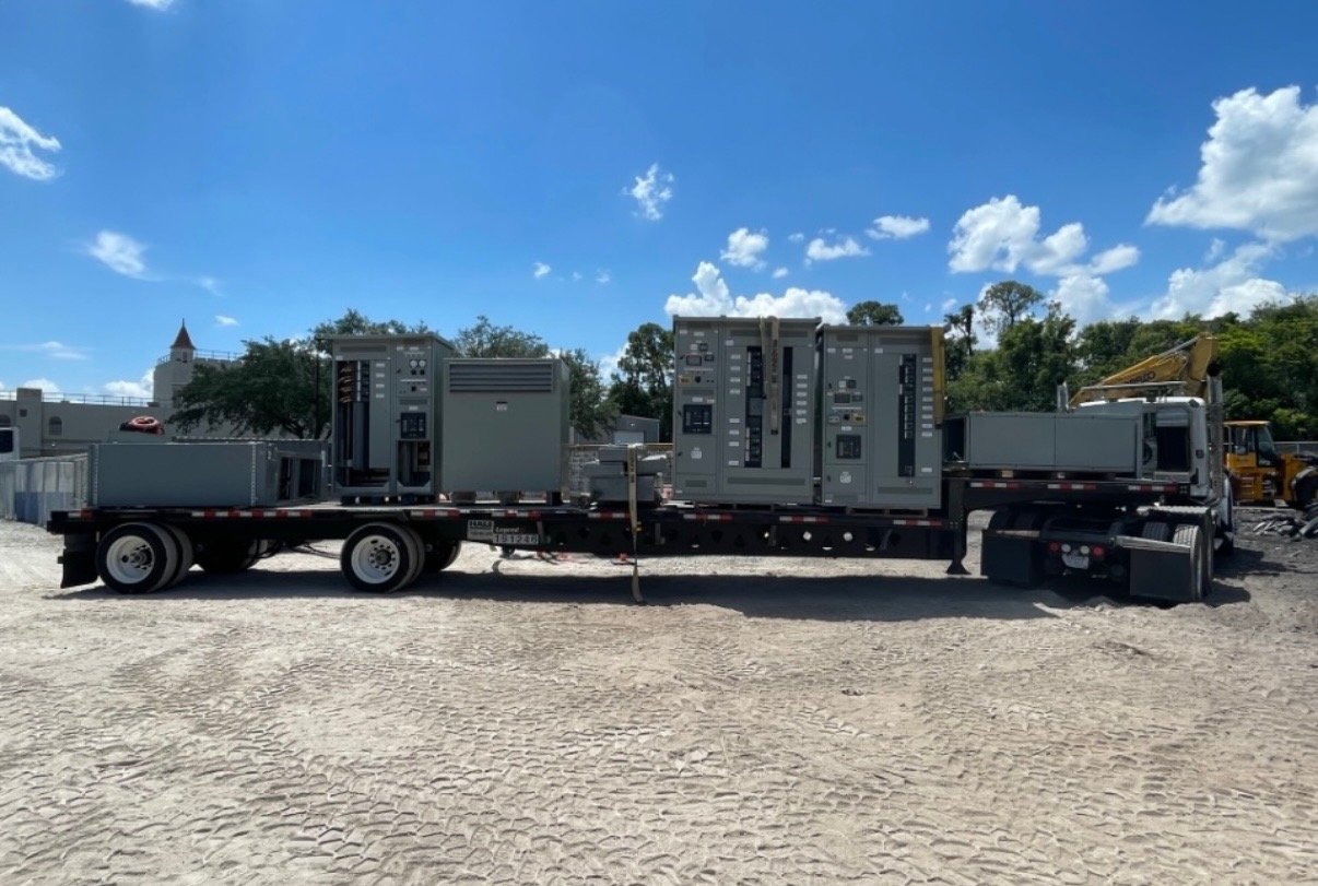
For Georgia projects, delivery planning should align with site access, receiving capacity, construction sequence, and the date approved drawings and installation information are needed. New equipment can be configured for the project, with American-made components and nationwide shipping options considered in the order scope. Confirm the destination, unloading constraints, delivery window, and required submittals before release; timing and availability are order-specific.
At turnover, the installing contractor, facility team, and responsible engineer should have the approved drawings, equipment identification, isolation information, and site procedures needed to plan future work. Establish who maintains revisions and labels and how changes to the one-line or source arrangement will be recorded. Delivery of switchgear supports the work process but does not verify an electrically safe condition.
Make verification part of the specification
Before approving a configuration, ask whether the intended work points are identifiable and accessible, which sources must be isolated, what drawings and labels will be supplied, and what constraints affect testing. Assign responsibility for reviewing those assumptions, updating site procedures, and confirming field conditions. Qualified personnel must select and use appropriate instruments and follow the facility’s approved process before work starts.
For a Georgia equipment inquiry, send the available one-line, voltage and source details, room or lineup constraints, preferred access and documentation requirements, delivery location, and project milestones. These details help scope a new switchgear or switchboard package around the verification needs of the actual installation. Request an engineering review of unresolved access or source questions before finalizing the order.