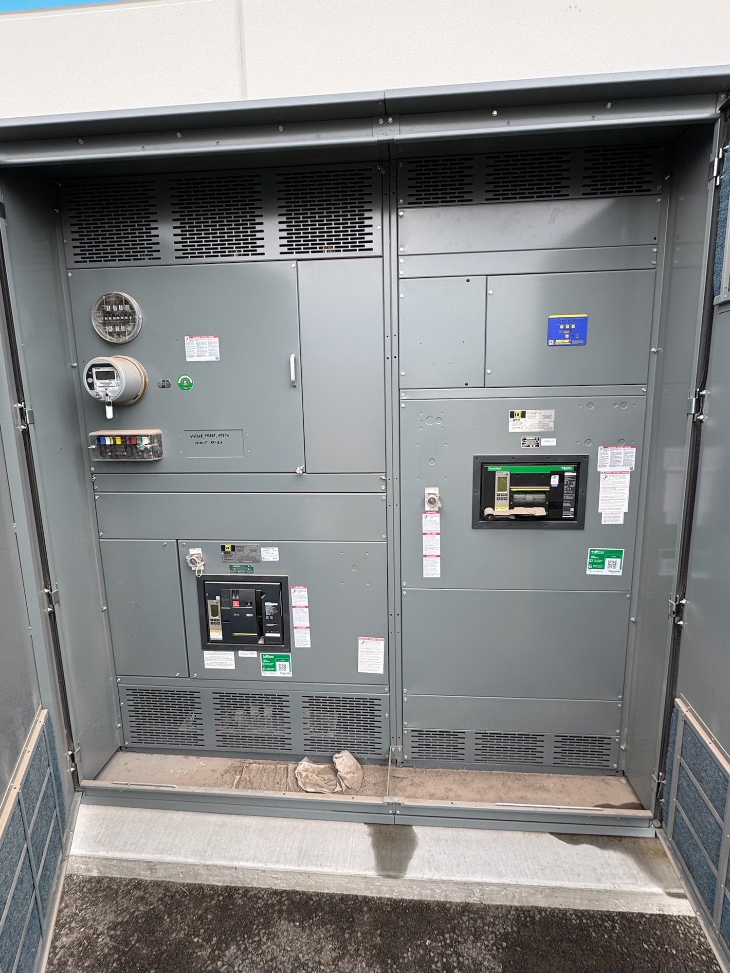
Confirm the system and load mix
A nominal 277/480-volt wye system provides 480 volts phase to phase and 277 volts phase to neutral. That makes it a practical distribution choice where compatible lighting operates at 277 volts and motors or other three-phase loads use 480 volts. Loads connected phase to neutral are not interchangeable with phase-to-phase loads, so schedules should identify voltage, phase, poles and connection for each circuit.
Share the service configuration and available drawings, including whether the requested assembly is service equipment or downstream distribution. Identify the source transformer or upstream equipment, incoming conductors, expected load, and any 208/120-volt loads served through separate equipment. Do not assume a 277/480-volt lineup can supply every building voltage directly; the design may require additional transformation and distribution.
Resolve neutral and grounding details
The neutral is important when the lineup supplies 277-volt lighting or other phase-to-neutral loads. Specify whether a neutral bus is required, its intended loading, and which feeders need neutral conductors. Discuss nonlinear electronic lighting drivers and other loads that may affect neutral current with the project engineer; do not size the neutral by assumption or infer its capacity from the phase bus rating.
Grounding depends on the system arrangement and the equipment’s location in the distribution system. Provide the grounding electrode and bonding design information, source and bonding point, and whether the switchgear is intended as service equipment. The responsible electrical engineer must establish the grounding and neutral-bonding scheme, and the authority having jurisdiction must review applicable requirements. Keep neutral and equipment-grounding functions distinct in schedules and drawings.
Choose ratings from the fault study
Specify nominal voltage, frequency, bus amperage, number of phases and wires, and the required short-circuit withstand or interrupting ratings for the assembly and its devices. Those values must follow the available fault current, system configuration and protective-device coordination study, not a general rule based on 480 volts. Include the study assumptions or source data so the design team can verify the requested ratings against the installation.
Circuit breakers, fuses, trip functions and settings should align with feeder conductors, connected loads, coordination objectives and the project’s protection study. Identify main and feeder device types, frame or trip requirements where established, spaces for future circuits, and any metering or control functions. Final device selection and settings require engineering review; a requested rating alone does not establish that a complete design is suitable for the site.
Define the assembly and connections
Clarify the intended lineup arrangement, main-device configuration, feeder count, bus requirements, cable or busway entry, and conductor termination space. State whether the installation needs top or bottom entry, front or rear access, a particular section sequence, or provisions to match adjacent equipment. Provide available room dimensions, access constraints and existing interface drawings when replacing or extending a distribution lineup.
For a new UL 891 switchboard assembly, confirm the project’s required standard and exact scope during specification review. UL 891 applies to switchboards; it should not be treated as a blanket listing for medium- or high-voltage switchgear. Describe any environmental, metering, communications or control requirements clearly, and have engineering confirm how they affect the proposed assembly. Options and availability depend on the final configuration.
Prepare the quote and Georgia handoff
For a useful quote, send the one-line diagram, load and feeder schedules, service details, fault-current or coordination information, grounding requirements, device preferences, enclosure and access constraints, and requested submittal documents. Note what remains undecided and who will approve it. Include the project location in Georgia, required delivery window, receiving hours, unloading capability and site access limits; these details help plan nationwide shipment without presuming a delivery date or site service.
Before release, align the approved drawings, equipment schedule and purchase documents on voltage, neutral and ground arrangement, bus and device ratings, circuit quantities, entry locations and options. Confirm the exact scope, component availability and production timeline for the order. Ask the engineer to resolve open grounding, fault-duty and protection questions before approval, then coordinate the Georgia receiving plan with the project schedule.