Identify the system, not just the voltage
In a typical 120/240-volt, single-phase, three-wire split-phase system, the two ungrounded conductors measure about 240 volts from line to line, while either conductor measures about 120 volts to the grounded neutral. This arrangement commonly serves a mix of 120-volt lighting and receptacle circuits and 240-volt loads. The service description should state the phase and wire count, not leave the manufacturer to infer them from the voltage alone.
A 120/240-volt high-leg delta system is three-phase, four-wire distribution. It provides 240 volts between phases and 120 volts from two phase conductors to neutral; the third phase, called the high leg, has a higher voltage to neutral. It is not interchangeable with split phase. Confirm the utility or existing service configuration, and identify conductors using the project’s approved drawings and applicable requirements.
Resolve high-leg details before equipment selection
On a high-leg delta service, the high leg must not be treated as a 120-volt conductor. The service documentation should identify which phase is the high leg and specify the required marking and termination arrangement. This matters when arranging branch circuits, selecting compatible devices and laying out the switchboard. Do not rely on an assumed phase sequence or wire color; obtain the engineer’s one-line diagram and project specifications.
Ask the engineer to confirm which loads require three-phase power, which require 240 volts, and which need 120 volts. Loads connected line to neutral must use only the suitable phases. A panel schedule that lists breaker sizes but omits connection voltage or phase can conceal a mismatch. Resolve these details before submittals so the proposed bus, neutral and circuit layout can be reviewed against the intended system.
Specify ratings and construction from project documents
For either arrangement, provide the required system voltage, phase, number of wires, frequency, service or feeder role, and grounding approach. Include the available fault current or the engineer’s required short-circuit rating, along with the overcurrent device and coordination requirements defined for the project. The appropriate rating and construction depend on the specific installation; they cannot be selected from “120/240 volts” alone.
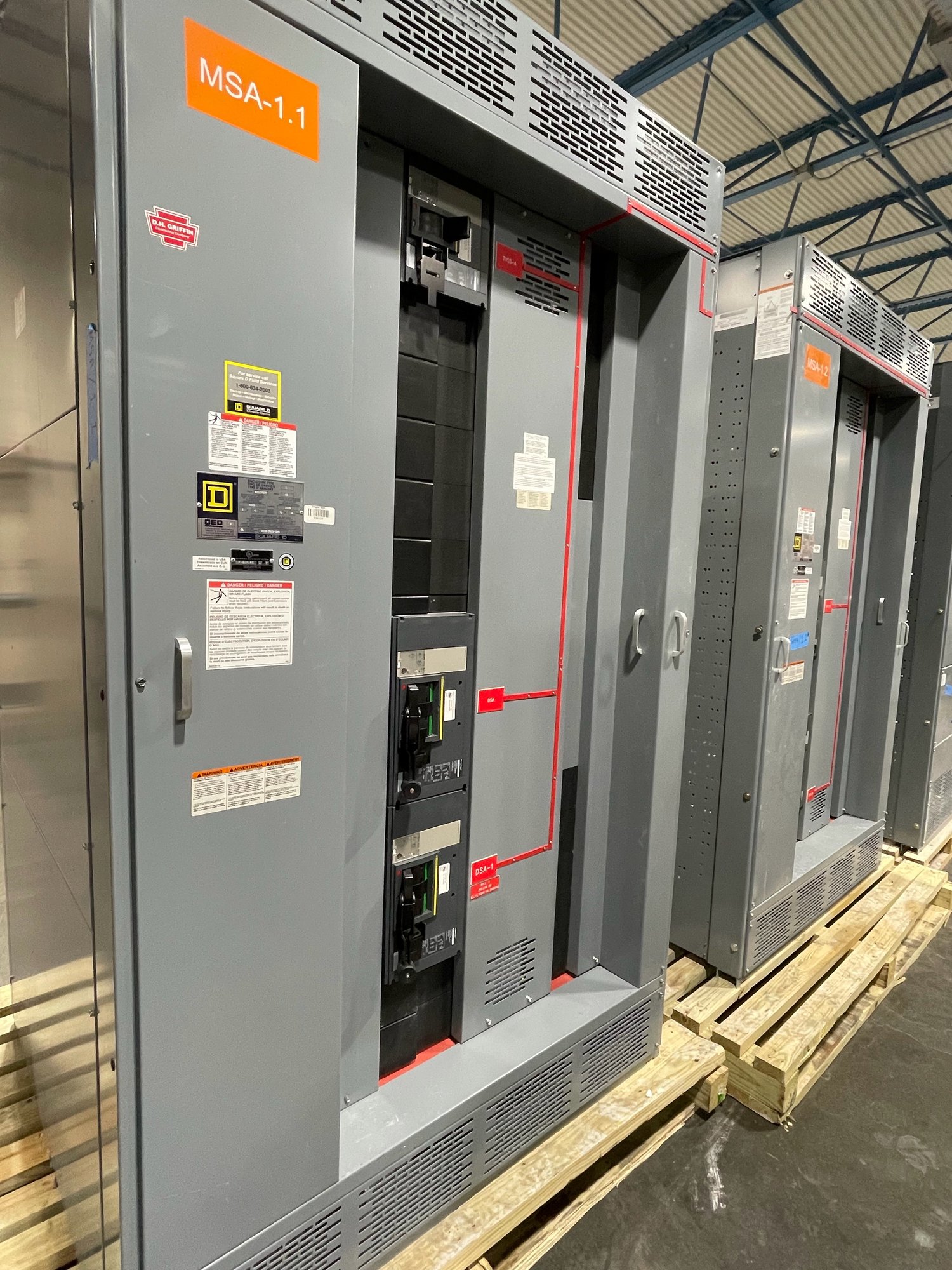
Describe the required incoming and outgoing connections, main device scope, branch-device count and types, neutral configuration, enclosure requirements, and any metering or control provisions. State whether the equipment is a switchboard assembly or another equipment type. UL 891 applies to switchboards; it is not a blanket listing for medium- or high-voltage switchgear. Confirm the requested scope and applicable evaluation requirements in the project documents.
Make load information useful for review
Provide a current load schedule that separates 120-volt, 240-volt single-phase and 240-volt three-phase loads where applicable. Include load descriptions, quantities, demand assumptions and any motor or other equipment data needed for device selection. For existing installations, identify known additions and removals rather than sending an old panel schedule as the sole basis for a new configuration.
For split phase, show how 120-volt loads are distributed between the two legs and how larger 240-volt loads connect. For high-leg delta, show the intended phase connections and mark line-to-neutral loads clearly. The design professional must determine load calculations, balancing and code requirements. Manufacturer review of a proposed configuration does not replace engineering approval or the authority having jurisdiction’s review.
Prepare a complete quote and submittal handoff
For a quote, share the one-line diagram, panel schedules, specifications, required ratings, enclosure and installation details, and the desired equipment scope. State explicitly whether the source is split phase or high-leg delta, and provide the high-leg identification when relevant. Include project location in Georgia, requested delivery timing and any site receiving constraints. Exact scope, availability and timeline are confirmed for each order.
Before release, compare the approved submittal with the service description, phase arrangement, conductor identification, load schedule, dimensions and connection points. Resolve deviations through the responsible engineer before fabrication. This handoff helps keep procurement documents, field installation plans and equipment configuration aligned without assuming an undocumented utility or building condition.
Plan delivery around the Georgia installation
Georgia projects may have different access, unloading and construction-sequence requirements. Provide the delivery address, receiving hours, site access limitations, unloading responsibility and any staging restrictions when planning the order. Nationwide shipping is available, while routing and timing depend on the confirmed equipment scope and shipment details. Coordinate delivery with the contractor’s installation schedule rather than treating a voltage label as a measure of readiness.
Before requesting pricing, verify the source configuration and assemble the one-line diagram, load schedule, required ratings and site delivery information. If records do not establish whether the system is split phase or high-leg delta, ask the serving utility or responsible engineer to confirm it. That single clarification can prevent a fundamental mismatch in the switchboard specification and provide a sound basis for engineering review and procurement.