Map the collection system before specifying equipment
A wind collection system gathers output from turbine generators through individual circuits, feeder runs, and a collector bus before power reaches the substation and the utility interconnection. Switching and protection equipment may be required at turbine interfaces, feeder junctions, collector buses, or other defined points. The one-line diagram should show which circuits must be isolated, how sections can be reconfigured, and where protection devices operate.
Start with the project’s electrical boundaries. Identify whether the requested equipment serves turbine-side circuits, a collection bus, an auxiliary system, or a substation interface. Clarify ownership and operating responsibility at each boundary, along with normal and alternate operating arrangements. These details establish what the assembly must connect, switch, and protect, and help avoid ordering equipment that does not match the actual scope.
Use study results to define protection interfaces
Collection-system fault current and protection behavior depend on the network, transformer connections, turbine converter characteristics, grounding, and utility conditions. Short-circuit, coordination, grounding, and arc-flash studies can inform interrupting and withstand requirements, protective-device selection, settings, and isolation strategy. Wind generation can also affect fault contribution and relay response in ways that differ from a conventional radial load feeder.
Do not select devices from nominal system voltage alone. Confirm the study assumptions, available fault-current values, clearing times, and any operating cases that affect equipment duty. The project engineer should establish protection functions and settings, including any required directional, differential, or communications-assisted schemes. Our configuration can be developed from the approved design inputs; final application and settings require review by the responsible electrical engineer and applicable authorities.
Resolve grounding, switching, and operating needs
Grounding method influences phase-to-ground voltages, fault detection, and insulation requirements. Share the system grounding arrangement and any grounding transformer or resistor details that affect the collection bus. Also identify whether switching is expected under load, what isolation points operators need, and whether the design calls for visible isolation, grounding provisions, interlocks, or remote operating interfaces. These functions must be coordinated with the overall system and operating procedures.
Wind sites may have long feeder runs, changing generation conditions, and maintenance needs that affect sectionalizing choices. Ask the engineer to define normal configuration, permitted alternate feeds, and the consequences of isolating a feeder or bus section. Document control power, metering, relay, communication, and terminal requirements as well. Those details help translate a single-line concept into a buildable assembly and reduce uncertainty during design review.
Coordinate assembly scope and applicable standards
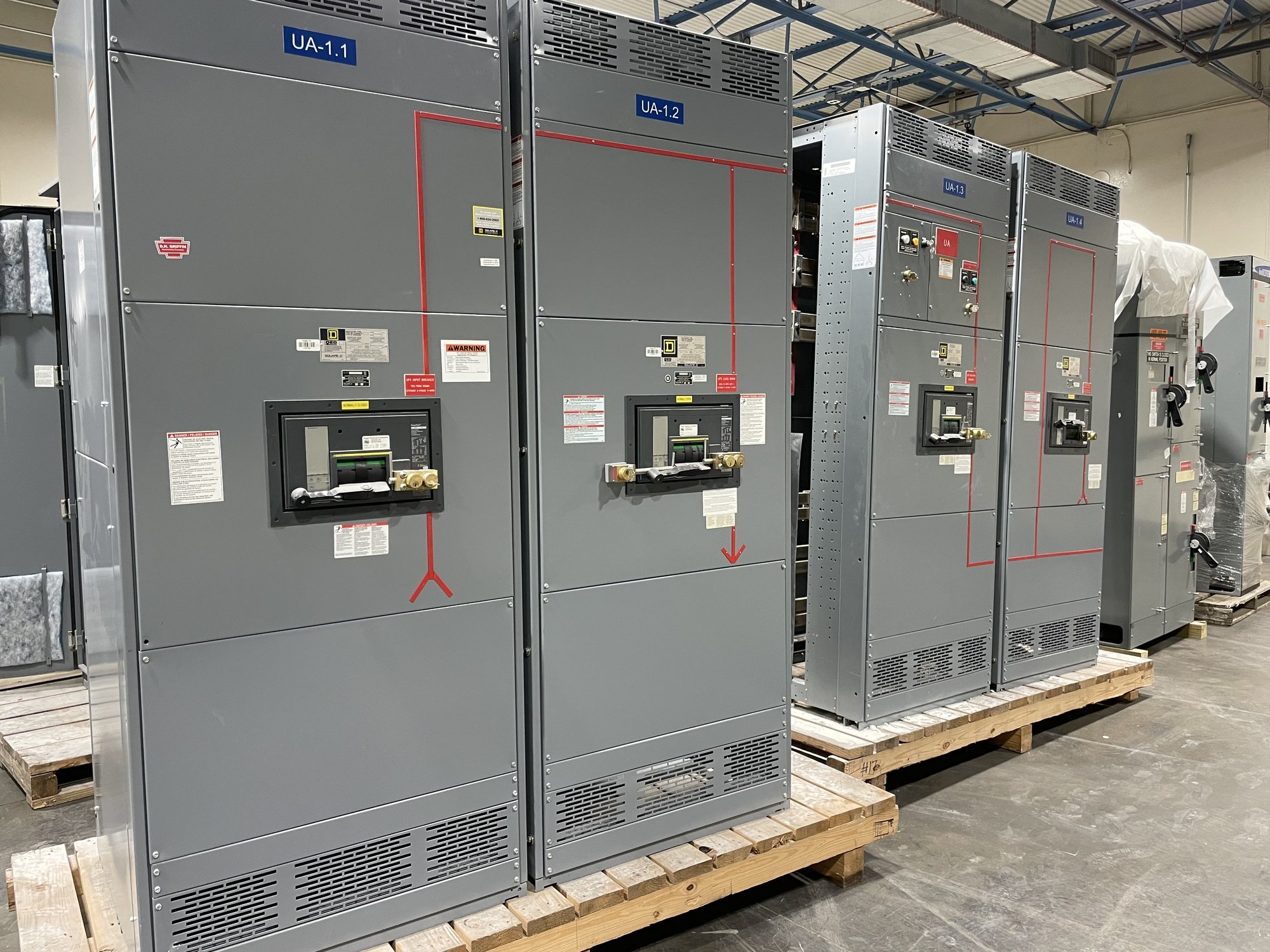
Specify the equipment boundary precisely: lineup arrangement, incoming and outgoing connections, bus requirements, protective devices, control wiring, metering, and any transition or interface sections. Provide available room dimensions, cable entry direction, termination approach, environmental conditions, and access constraints. If the project includes medium-voltage collection equipment, identify its applicable equipment standards and ratings separately; UL 891 applies to switchboard assemblies and is not a blanket listing for medium- or high-voltage switchgear.
For a quote, share the current one-line diagram, equipment schedule, study data, project specifications, and required submittal documents. Include system voltage, continuous current, fault duty, grounding, protection philosophy, quantities, requested delivery location, and the date equipment is needed on site. Note open design items rather than treating assumptions as final. Exact configuration, component availability, and schedule are confirmed for each order.
Plan procurement around Georgia site logistics
Georgia delivery planning should account for the project’s construction sequence, receiving arrangements, and route from the delivery point to the installation location. Confirm whether the site can accept the shipment, how equipment will be unloaded and stored, and whether phased delivery aligns with civil, electrical, and commissioning work. Nationwide shipping can support Georgia projects, while delivery timing and shipment details depend on the confirmed order and destination.
The procurement handoff should connect the approved electrical design to fabrication and installation. Establish who approves drawings, who reviews protection interfaces, and how changes to ratings, cable entries, or control requirements will be managed. Before release, reconcile the latest one-line and schedules with the purchase specification so the delivered assembly matches the intended collection-system boundary.
Turn project inputs into a defined build
A useful starting package includes the one-line, fault and coordination study outputs, grounding details, equipment schedule, interface list, site constraints, and procurement milestones. Add the project’s required standards, submittal expectations, and Georgia delivery address or receiving plan. With those inputs, we can review the requested scope, identify information needed to complete configuration, and confirm availability and timing for the specific order.
Before requesting pricing, ask the project engineer to confirm the operating cases and protection basis, then identify any unresolved assumptions for review. Share those decisions with procurement and the equipment supplier together. This gives the team a practical path from study results to a coordinated collection-system assembly, while leaving final design approval, installation, and energization to qualified professionals under the project’s applicable requirements.