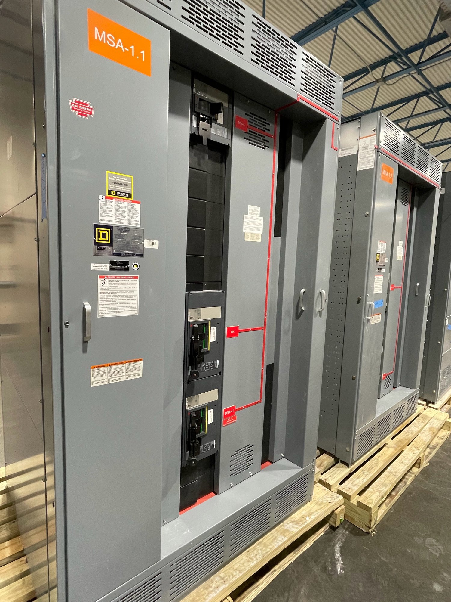
Map the complete power path
Start by documenting the electrical path from each source through the UPS and onward to the loads. Identify the normal input, any separate bypass input, UPS output, maintenance bypass route, and downstream distribution. A one-line diagram should show source relationships, transfer points, grounding approach, and the boundaries between UPS equipment and switchgear. This makes it easier to determine which assemblies are needed and where isolation and protection belong.
Clarify whether the project uses a single UPS module, parallel modules, redundant systems, or multiple independent power paths. Record the intended operating modes and which loads must remain energized during maintenance or a source transition. These details affect bus arrangements, feeder counts, device selection, and physical separation. The switchgear scope should follow the engineered sequence of operation rather than assume a standard UPS topology.
Coordinate UPS inputs and sources
For each UPS input, provide voltage, phase, frequency, conductor arrangement, rated input current, and the upstream source. If rectifier and bypass inputs use separate feeders, identify whether they share a source, come from independent sources, or include an upstream transfer scheme. Also provide the UPS manufacturer's connection requirements and any limits on upstream protective-device type, size, or settings. The final selection depends on the full system design, not only the UPS rating.
Input coordination must account for the available fault current at the switchgear and the protective devices ahead of the UPS. Ask the engineer to establish fault-current values, protection objectives, and coordination requirements for normal and bypass paths. Do not assume that a device suitable for the UPS input will also serve the bypass circuit, or that two paths can be combined without affecting selectivity or operating procedures.
Define output distribution and bypass
On the UPS output side, list every required feeder, its load description, voltage, phase, conductor details, and protective-device requirements. Distinguish critical loads from loads that may be shed, and indicate whether downstream panels or distribution assemblies are part of the equipment package. Load schedules and demand assumptions help establish the intended bus and feeder arrangement; final ratings and protection remain subject to engineering review.
A maintenance bypass can route power around the UPS so the UPS can be isolated for service, but its arrangement must match the system's operating sequence. Specify whether bypass is integral to the UPS or provided in separate switchgear, how interlocking is intended, and what source supplies the bypass path. Document switching steps and required isolation points with the responsible designer and UPS supplier. The equipment configuration should support that approved sequence without implying that bypass operation is risk-free.
Check fault-current limits and assembly scope
UPS output fault contribution may differ from the utility or generator source and may be limited by the UPS controls. That behavior does not remove the need to evaluate fault current at each switchgear location, including bypass operation and alternate source conditions. Provide source data, transformer information, generator details where applicable, and the engineer's available-fault-current study. Protective-device interrupting ratings and assembly suitability must be established for the actual system conditions.
UL 891 applies to switchboard assemblies; it is not a blanket listing for medium- or high-voltage switchgear. For a low-voltage switchboard scope, identify the applicable assembly requirements and requested documentation. State whether the project needs a main device, feeder devices, metering, control wiring, communications provisions, or specified compartmentation. Each rating, certification, and configuration must be confirmed for the particular equipment being quoted.
Prepare a useful quote package
For a quote, share the latest one-line diagram, equipment schedules, UPS submittal or interface data, load list, fault-current information, and project specifications. Include required bus and device ratings, enclosure conditions, cable entry and termination preferences, metering or communication points, and any space constraints. Mark assumptions, alternates, and items assigned to other suppliers so the proposed switchgear scope can be reviewed without guessing.
Also provide the project location in Georgia, required ship-to point, site access considerations, and the date equipment is needed at the project. We build new equipment with American-made components where specified and can configure assemblies to the documented application. Exact component scope, availability, and schedule are confirmed for each order; Georgia delivery planning should be coordinated with the construction sequence and receiving capabilities.
Close the interface before release
Before production release, align the switchgear drawings with the UPS supplier's connection details, the engineer's one-line and protection decisions, and the contractor's cable and installation plan. Resolve terminal locations, control interfaces, bypass interlocks, device settings responsibilities, and any required field connections. Confirm who will review and approve each interface document, and route changes through the project team so revisions do not leave conflicting requirements.
To move the application forward, send the one-line diagram, UPS input and output data, bypass sequence, fault-current study, feeder schedule, and Georgia delivery requirements together. Identify unresolved design decisions rather than treating them as settled. This gives the manufacturer a practical basis to define the new switchgear configuration, flag information still needed, and confirm the equipment scope and timing before the project depends on it.