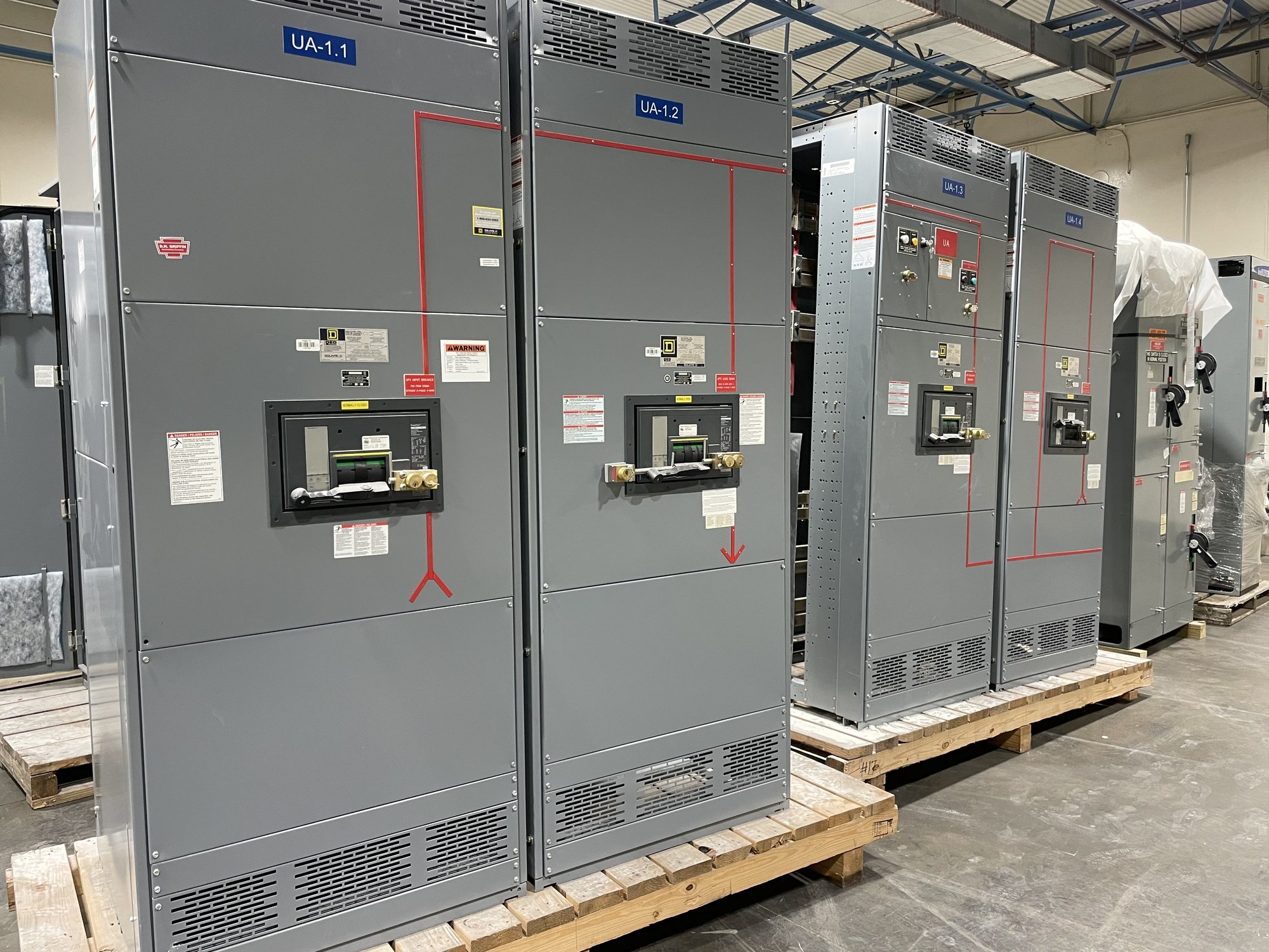
What an undervoltage release does
An undervoltage release is a mechanism associated with a circuit breaker that responds when its control voltage falls below its operating threshold. Depending on the breaker and control arrangement, loss of that voltage can cause the breaker to open or prevent it from closing. The release is not the same as an overcurrent trip: it responds to inadequate control voltage, not directly to excessive load current.
The control source matters. A release may be supplied from the circuit being controlled or from a separate control-power source, and those arrangements produce different behavior during a disturbance. Confirm the source, nominal voltage, acceptable operating range, and what happens if control wiring or the source fails. The selected breaker and release must be compatible with the switchboard design and intended operating sequence.
Define the response to a supply interruption
Start with the required state of each load when voltage falls or disappears. Some processes need a breaker to open so motors and other loads do not attempt to restart unexpectedly. Other applications may need continuity through a brief dip, with the control scheme distinguishing a transient disturbance from a sustained loss. Do not assume that every load should behave alike; process requirements and equipment manufacturer instructions should inform the sequence.
Specify the voltage condition and timing that should initiate action, along with the desired breaker response. Ask whether the release must trip on complete loss, respond to a defined undervoltage condition, or tolerate a momentary interruption. Actual thresholds and delays depend on the selected device and its approved application. Engineering review should account for control-power behavior, expected disturbances, and the consequences of opening or holding the breaker.
Plan what happens when power returns
Restoration of supply does not necessarily mean a tripped breaker will reclose. Many undervoltage arrangements require a manual reset or a separate close command after voltage returns. This can help prevent an unexpected restart, but it may leave critical loads out of service until an operator follows the required procedure. Establish who or what is permitted to initiate reclosing and whether the process requires inspection or interlocks first.
If automatic restoration is required, treat it as a coordinated control-system function rather than an assumed feature of the release. Define which loads may restart, in what order, and with what delay or permissive conditions. Consider motor inrush, process dependencies, generator or transfer-switch sequences, and the possibility that several loads could otherwise reconnect together. The project engineer should confirm that the sequence matches the facility’s operating and safety requirements.
Coordinate release, breaker and control circuit
For a new switchboard assembly, identify the breaker location and function, the release operating voltage, the source of control power, and any required auxiliary contacts or indication. Clarify how loss of control power should be annunciated and whether remote status, local indication, or supervisory-system points are needed. Also identify interfaces with transfer equipment, emergency systems, process controls, and any lockout or permissive logic that affects closing.
An undervoltage release adds control wiring and device compatibility considerations to the breaker selection. Drawings should show the control source, protective devices, terminal points, and intended trip and close logic. Confirm available control power under normal and abnormal conditions, including whether it remains available during the very supply event that is meant to trigger operation. Final device selection and settings require engineering review and coordination with the equipment application.
Information to provide for a quotation
To scope new equipment accurately, provide the one-line diagram, system voltage and configuration, board lineup requirements, breaker functions, and available fault-current information for engineering review. For each affected breaker, describe the load served and the required response to a brief dip, sustained undervoltage, complete loss, and restoration. Include control-power voltage and source, existing or planned transfer equipment, and any desired alarms or remote indications.
Share the required operating sequence, project schedule, drawing and submittal needs, delivery location in Georgia, and site receiving constraints. Identify any specifications or owner standards that govern control circuits or restart behavior. These details help the manufacturer develop a configuration for review rather than assume a generic release arrangement. Exact scope, component availability, and production and delivery timing are confirmed for each order.
Carry the sequence through handoff
Before release to production, review the approved drawings for release voltage, control source, trip behavior, restoration logic, indications, and terminal interfaces. Resolve any mismatch between the one-line diagram, control schematics, breaker schedule, and written sequence. For UL 891 switchboard assemblies, that standard applies to the switchboard assembly; it does not establish a blanket listing for other classes of switchgear or replace project-specific engineering review.
At installation and commissioning, qualified personnel should verify wiring and operation against approved documents and the equipment instructions, including behavior during simulated loss and restoration where the test plan permits. For a Georgia project, coordinate shipment timing and receiving arrangements with the site schedule; nationwide shipping options do not establish a guaranteed delivery date. Before requesting a quote, write down the intended state of every affected breaker during loss and after restoration, then provide that sequence with the project documents.