Start with the generator and its operating modes
A relay application begins with machine data, not a generic list of functions. Share the generator type, rated output, terminal voltage, frequency, winding and grounding arrangement, excitation system, and manufacturer protection recommendations. Include the operating modes the project expects, such as isolated standby, parallel operation with other generators, or operation alongside the utility. These details affect which conditions the relay can detect and what response is appropriate.
Protection objectives also differ by consequence. A facility may need to limit damage to the generator, maintain service to selected loads, or separate from a utility connection when operating conditions require it. Identify which alarms, trips, lockouts, and transfer actions are intended, and which devices perform them. Relay functions must be coordinated with generator controls, breaker trip circuits, transfer equipment, and upstream protection rather than specified in isolation.
Select functions for actual fault and abnormal conditions
Common generator protection functions address phase and ground overcurrent, differential faults, voltage and frequency deviations, reverse power, loss of field, negative-sequence current, and thermal stress. The applicable set depends on machine size and construction, grounding method, system topology, and the level of protection already provided by the generator controls. For example, ground-fault detection depends on how the neutral is grounded and where current or voltage sensing is installed.
Not every project needs every function, and a function name alone does not define a complete scheme. Confirm whether the relay must trip the generator breaker, initiate a lockout, signal the engine or turbine controller, or provide an alarm for operator action. Where a function is omitted or handled by another device, record that division of responsibility. The protection engineer should verify coverage, coordination, and failure response for the complete system.
Settings follow the machine and interconnection
Pickup values, time delays, curves, and trip logic must reflect generator capability and system behavior. Obtain manufacturer limits for voltage, frequency, current, thermal withstand, and loss-of-field operation, along with the studies and coordination criteria used for the project. Settings that are too sensitive can cause unwanted trips during permitted operating conditions; settings that are too permissive can delay action during a damaging condition. Do not copy values from another generator without engineering review.
The interconnection scheme changes what the relay sees and what it must do. A generator connected through a transformer, operating in parallel with utility power, or sharing a bus with other sources may require different sensing, directional elements, or coordination than an isolated unit. Provide a one-line diagram showing breakers, transformers, grounding points, CT and VT locations, and utility demarcation. Utility interconnection requirements and approved study results may constrain settings and trip logic; confirm the controlling documents before finalizing the design.
Specify sensing, logic, and records
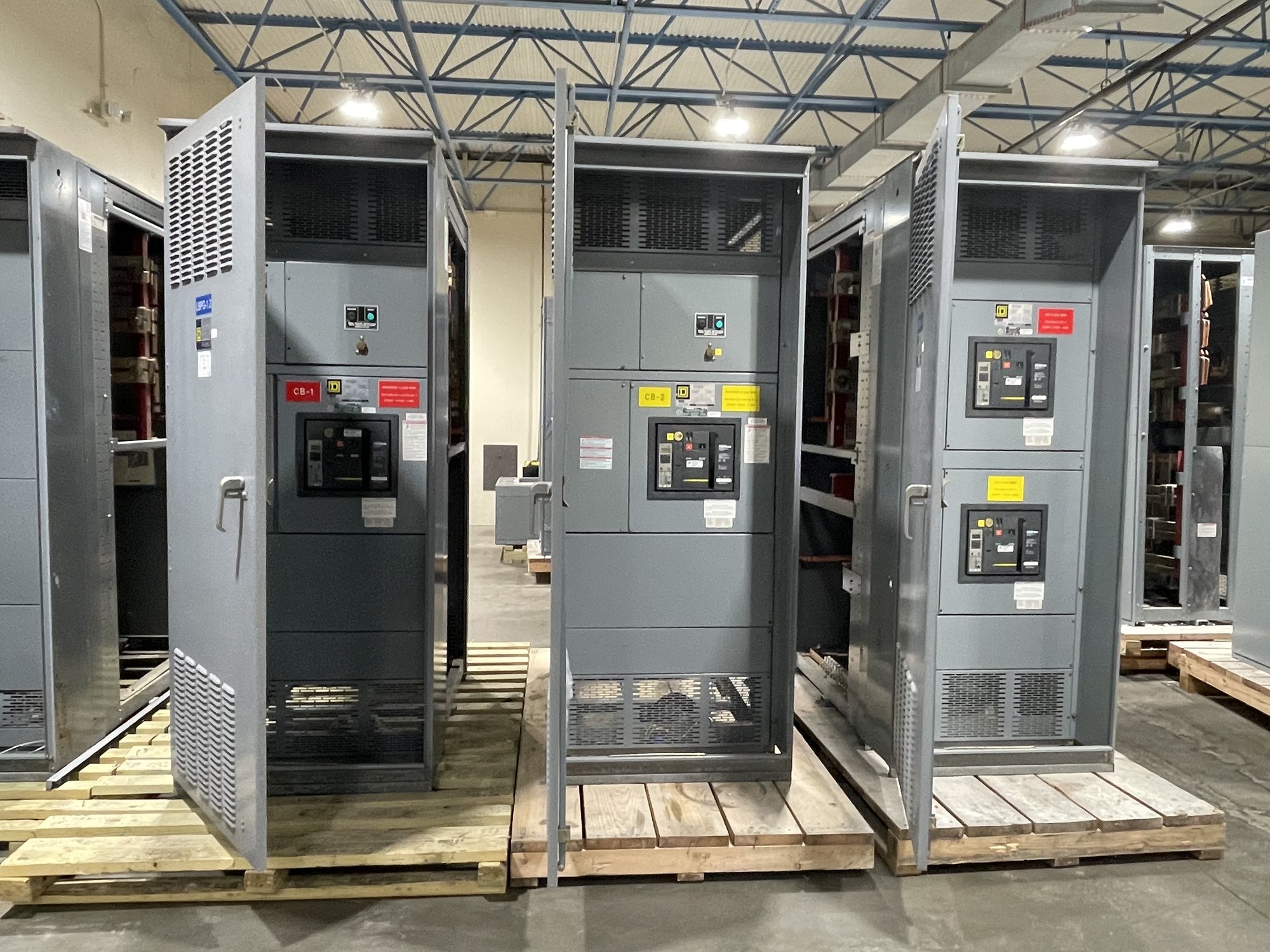
For a relay and switchgear package, identify the required CT and VT ratios, accuracy and burden information where available, polarity, connection, and intended relay inputs. Describe auxiliary power, communications, event records, metering, and remote status needs. Confirm whether the relay is a new standalone device or part of a broader generator breaker lineup, and provide available panel dimensions or equipment interface details. These inputs help establish a configuration that can be reviewed against the drawings.
Request a clear definition of what is included: relay model or approved requirements, programmed functions, settings responsibility, wiring scope, drawings, and factory checks. If the protection engineer will provide final settings after equipment selection, state that at quote stage and identify the information needed for configuration. A protection package should not imply that the relay itself establishes a complete or approved scheme; engineering and the authority having jurisdiction review the application.
Plan procurement and Georgia project delivery
For a useful quote, send the one-line diagram, generator data sheet, operating sequence, interconnection documents, protection study or coordination criteria, and preferred equipment interfaces. Include quantities, project schedule, site delivery location in Georgia, and any receiving constraints such as delivery hours or offloading responsibility. If details are not yet settled, identify open decisions and the person responsible for resolving them so the proposed scope can separate confirmed requirements from assumptions.
We manufacture and supply new protection and switchgear equipment in the United States, with custom-built configurations, American-made components, and nationwide shipping. The exact scope, component availability, and production and delivery timeline are confirmed for each order. For UL 891 switchboard assemblies, that standard applies to the switchboard assembly; it does not establish a blanket listing for medium- or high-voltage equipment or validate a generator protection design.
Close the design gap before release
Before equipment release, reconcile the approved one-line, relay function list, CT and VT data, trip matrix, settings responsibility, and interface wiring. Confirm who will provide and approve final settings, who will test the scheme, and how changes from utility review or field conditions will be captured. The project engineer should resolve discrepancies before fabrication or commissioning rather than relying on assumptions embedded in a quote.
To begin, provide the generator and interconnection documents, state the intended operating modes, and identify the required trip and alarm actions. Ask us to quote the defined equipment scope and flag missing inputs that affect configuration, schedule, or delivery to Georgia. This gives the engineering team a concrete basis to complete the protection design and the purchasing team a scope it can evaluate.