Define what independence must protect
A two-path arrangement provides separate routes for power, commonly labeled A and B, so a fault, outage, or planned maintenance on one route does not automatically interrupt loads assigned to the other. The required outcome should come first: identify which loads need one path available, whether transfer is expected, and what operating condition the design must support. A second feeder alone does not establish meaningful redundancy.
Document the intended sources, normal operating state, transfer method, and loads served by each path. Clarify whether paths are normally isolated, operate in parallel, or connect through a transfer device, and identify who controls switching. These choices affect equipment arrangement, protection coordination, interlocking, and procedures. The facility’s electrical engineer should establish the design basis and review it with the authority having jurisdiction.
Trace A and B through the complete system
Independence must be checked from utility service or onsite generation through transformers, switchgear, distribution panels, branch circuits, and the final load connection. Trace each route on current one-line diagrams and compare the physical paths. Look for shared buses, common protective devices, a single transformer, common control power, or a transfer point that could disable both routes. A diagram can conceal shared infrastructure unless the equipment and operating states are examined.
Physical separation also matters. Routes may converge in a room, duct bank, cable tray, fire area, or other location exposed to one event. Shared grounding, monitoring, communications, or control circuits may create dependencies even when power conductors are separate. The project team should define which common elements are acceptable and document why; complete separation may be impractical or unnecessary for the required availability.
Resolve transfer and operating behavior
Specify what happens when a source or path becomes unavailable. A load may transfer automatically, require operator action, or remain on its assigned path while a second source is restored. State the permitted interruption, transfer sequence, preferred source, and conditions for return to normal. If transfer equipment can connect sources, engineering must address source compatibility, interlocking, protection, and whether parallel operation is permitted.
Operating procedures should cover maintenance and abnormal conditions, not only normal service. Ask how isolation is verified, what alarms indicate loss of a path, and whether controls remain available when one route is de-energized. These requirements influence switchgear compartments, metering, control wiring, and the location of devices. Final settings and operating instructions depend on the engineered system, not a general two-path template.
Specify equipment around the architecture
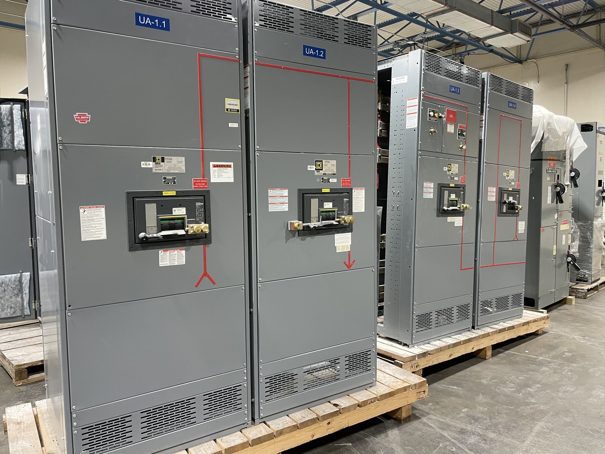
For a new equipment quotation, provide the one-line diagram, source and load schedule, system voltage, available fault-current information, protection requirements, and the intended A/B arrangement. Identify whether the scope includes incoming equipment, bus sections, feeder devices, transfer equipment, metering, controls, or only selected assemblies. Include enclosure and installation constraints, cable entry preferences, and required interfaces with existing equipment.
UL 891 applies to switchboard assemblies; it is not a blanket listing for medium- or high-voltage switchgear. State the equipment type and applicable project requirements explicitly, then have the engineer confirm ratings, construction, and acceptance criteria for the actual application. Custom-built configurations and American-made components can be considered for the specified scope. Component availability, exact configuration, and schedule are confirmed for each order.
Coordinate procurement and Georgia delivery
Procurement decisions should preserve the design intent while making interfaces clear. Share equipment room dimensions, access and handling limits, connection points, site voltage, and any required integration with existing protection or controls. Identify submittal milestones, drawing review responsibilities, testing and documentation expectations, and who approves deviations. Early resolution of these details helps avoid ordering equipment that fits electrically but conflicts with the room or installation sequence.
For Georgia projects, provide the delivery location, site access conditions, requested delivery window, and whether equipment must arrive in a particular sequence. Nationwide shipping can support projects across the state, but freight timing and order scope are confirmed for each project. Coordinate delivery with the contractor’s receiving plan, storage conditions, rigging arrangements, and construction schedule rather than assuming equipment can be unloaded or staged at any site.
Make independence verifiable at handoff
Before release and commissioning, compare approved drawings with the delivered equipment and installed routes. Confirm device designations, source and load assignments, control connections, interlocks, and the physical separation assumptions used in the design. The commissioning plan should test normal and abnormal sequences within an approved procedure, including loss and restoration of each path where applicable. Qualified personnel should perform testing and energization under the project’s safety and authority requirements.
For a quote, send the one-line diagram, load priorities, source details, transfer expectations, equipment scope, site constraints, and Georgia delivery requirements. Ask the design team to mark every shared component between A and B and decide whether each is acceptable. That review gives procurement a clearer equipment specification and gives the installation team a practical basis for verifying the intended independence.