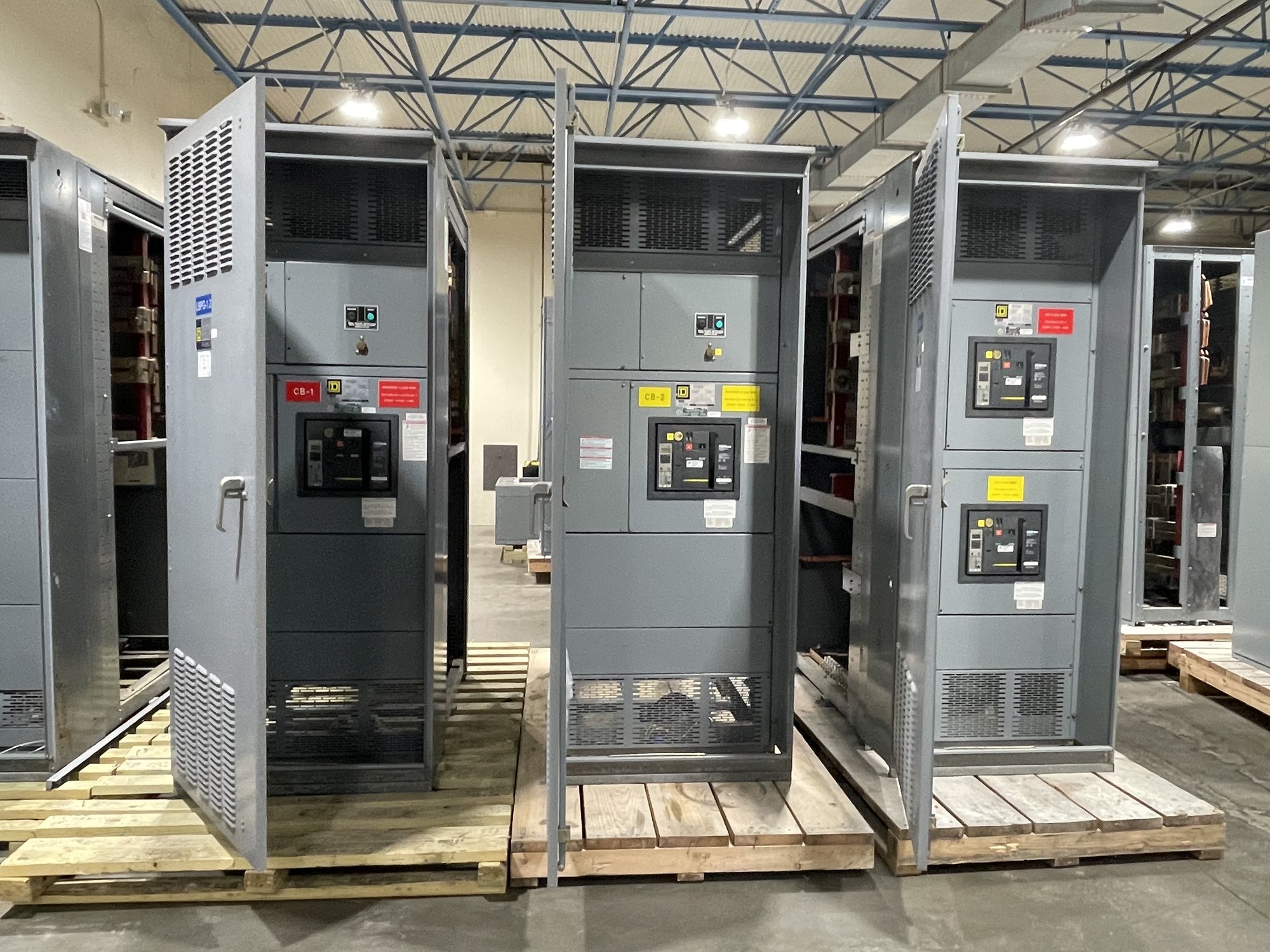
Define what N+1 means for your load
N+1 means a system has one more capacity unit than the number required to serve its defined load. If a design needs N units operating, it includes one additional unit so the intended load can still be supported when one unit is unavailable. The key phrase is defined load: the calculation depends on which loads must remain energized, their demand, and how capacity is divided among equipment.
For example, a facility may plan several distribution sections so that the remaining sections can carry designated critical loads after one section is removed from service. That does not automatically mean every building load can continue operating, or that each remaining section has adequate capacity. Engineers must establish load priorities, demand assumptions, transfer arrangements, and operating limits before labeling a design N+1.
Separate capacity redundancy from path redundancy
Extra capacity in a switchboard or other equipment does not by itself create an alternate route for power. A redundant source, bus, feeder, or section only helps if the system has a means to connect the required load to it and the components along that route can carry the load. A single upstream source, common bus, control circuit, or feeder can remain a point of failure even when downstream equipment has spare capacity.
Review the complete one-line diagram and identify the specific failure or outage the design is intended to tolerate. Ask whether the requirement covers loss of one distribution unit, one feeder, one source, or another defined event. Also determine whether transfer is manual or automatic, whether loads can be shed, and whether electrical or mechanical interlocks and operating procedures affect the available configuration.
Test the maintenance scenario, not just the nameplate
N+1 may support maintenance while designated loads remain in service, but only if the equipment can be isolated and the remaining arrangement can carry those loads under the planned operating conditions. Confirm how maintenance isolation works, which compartments or sections are affected, and whether bus ties or alternate feeds are part of the intended operating plan. The design should state what remains energized and what must be shut down.
A useful review considers credible outages and maintenance states one at a time. If one unit is already out for service, a second failure may exceed the intended redundancy. Check load growth, starting currents, demand variation, environmental conditions, and any derating or coordination requirements identified by the project engineer. N+1 does not eliminate the need for qualified personnel, approved procedures, or review by the authority having jurisdiction.
Specify the assembly around the operating concept
For a new UL 891 switchboard assembly, provide the approved one-line diagram, service and distribution arrangement, system voltage and phase, available fault-current information, required bus and device ratings, and the loads assigned to each section. UL 891 applies to switchboard assemblies; it is not a blanket listing for medium- or high-voltage switchgear. The project engineer must establish applicable standards, ratings, and design requirements for the complete system.
Describe how sections connect, what isolation and tie functions are required, and which loads must be supportable in each normal and maintenance state. Include metering, protective-device, enclosure, cable-entry, and space requirements where defined. If the operating concept is still under development, identify open decisions rather than treating assumed transfer logic or spare capacity as settled scope.
Make procurement decisions with limits visible
Compare proposals against the same load basis and outage scenario. Ask what capacity remains after the specified unit is unavailable, which loads are included in that calculation, and what operating conditions or assumptions govern the result. Confirm whether future expansion is intended as installed spare capacity, reserved physical space, or a later equipment addition; these are different procurement choices and may have different implications for connections and layout.
For a manufacturer quote, share the project location in Georgia, required delivery point, schedule milestones, approved drawings or current design documents, and the exact equipment scope. Include anticipated changes, site constraints affecting dimensions or shipping, and any required submittals. American-made components, custom-built configurations, and nationwide shipping can be discussed for the order, while availability, exact scope, and timeline are confirmed individually.
Carry the redundancy intent through handoff
The final documents should connect the N+1 claim to an explicit operating case: the load served, the unit unavailable, the remaining path, and any required transfer or load-shedding action. Keep the one-line diagram, equipment schedule, control descriptions, and operating procedures consistent. Resolve who approves the design assumptions and how revisions will be reviewed before equipment configuration is finalized.
Before requesting a quote, write down the critical load, the single outage or maintenance condition the design must tolerate, and the equipment or paths that must remain available. Send those assumptions with the one-line diagram, ratings, location, and schedule needs. This gives the manufacturer a concrete basis to scope a new assembly and lets the project team identify unresolved engineering decisions before procurement.