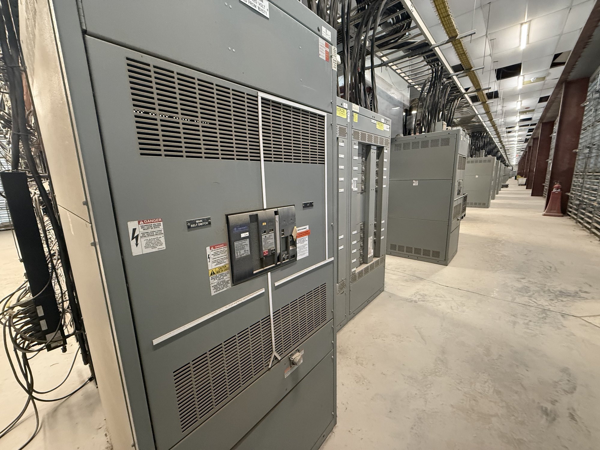
How the differential zone works
A differential relay measures current from current transformers (CTs) placed on the transformer’s sides and compares the values after accounting for their magnitude and phase relationship. Under normal load or an external fault, the adjusted currents should balance closely. A mismatch above the relay’s operating threshold indicates that current may be flowing into a fault within the protected zone, such as a winding fault or an internal lead fault.
The zone’s boundaries depend on where the CTs sit in relation to the transformer and associated breakers. CT placement can leave connections outside the differential zone or create overlap with bus, feeder or backup protection. Define the transformer terminals, breaker locations, grounding points and intended protection boundary before specifying the relay or switchgear interfaces. The protection engineer should confirm coordination with the complete system design.
CT ratios and accuracy
CT primary ratios must suit the transformer’s rated currents on each winding, which differ with voltage and winding configuration. The relay uses those ratios, transformer ratings and tap information to scale the measured currents for comparison. Specify CT ratios, secondary current, accuracy class, burden and intended relay input together; a ratio selected without checking the full measurement chain can compromise sensitivity or create excessive mismatch during load and fault conditions.
Provide transformer MVA, winding voltages, phase count, frequency and tap range, along with available CT nameplate and test data if the transformer is existing. For new equipment, identify whether CTs are furnished in the switchgear, at the transformer, or by another package. Confirm secondary wiring, grounding and terminal requirements at the interface. The responsible protection engineer must verify CT suitability and settings against actual equipment data.
Winding connection and phase compensation
Winding connections determine phase displacement and influence how the relay compares currents. A delta-wye transformer, for example, introduces a phase shift that must be represented in relay compensation. Modern numerical relays commonly apply this compensation in settings, but the engineer still needs the transformer vector group or connection, winding orientation and phase sequence. Incorrect assumptions can produce a differential signal during ordinary load rather than a dependable comparison.
Grounding also matters. Identify which neutrals are grounded, the grounding method and whether neutral CT inputs or restricted earth-fault protection are part of the scheme. Transformer tap changers can change the ratio across the operating range, so disclose the tap range and normal operating position. The relay’s restraint and compensation approach must suit those facts; do not assume a generic connection or setting applies to every transformer.
Inrush, external faults and restraint
Transformer energization can produce magnetizing inrush, with a current profile that differs substantially from balanced load current. Differential relays use restraint or blocking methods, often informed by harmonic content or waveform characteristics, to avoid an unwanted trip during energization while remaining responsive to internal faults. Ask which inrush logic is available, how it behaves during sympathetic inrush or overexcitation, and how settings will be validated for the actual transformer and system.
Through-fault current can also expose CT saturation, causing unequal secondary currents even when the fault is outside the protected zone. Review CT performance, relay bias characteristics and coordination with upstream and downstream protection. Differential protection does not replace overcurrent, ground-fault, thermal or mechanical protection where those functions are required. The project engineer should define the complete protection scheme and confirm settings using system studies and manufacturer data.
Specify the equipment and interfaces
For a switchgear quote, share the transformer nameplate or datasheet, single-line diagram, winding vector group, grounding details, CT schedules and relay requirements. Include bus arrangement, breaker type and location, control power, communications protocol, trip and alarm contacts, metering needs, enclosure conditions and any required test provisions. Identify who supplies the transformer-side CTs, relay, wiring and commissioning settings so the scope has clear boundaries.
State whether the assembly is a new UL 891 switchboard application or another switchgear configuration; UL 891 applies to switchboards and is not a general listing for medium- or high-voltage switchgear. Provide system voltage and project requirements for engineering review rather than presuming a rating or approval. We build new equipment with custom configurations and American-made components where specified; exact scope, component availability and schedule are confirmed for each order.
Georgia project handoff
For Georgia delivery, share the site location, receiving access, unloading arrangements, required delivery window and coordination constraints such as construction sequencing or transformer setting dates. Nationwide shipping can be arranged for the configured equipment, but the project team should confirm the shipment scope and timing against the order details. Include the electrical contractor, engineer and any transformer or protection-package supplier in interface reviews before drawings are released.
A useful handoff package includes approved one-lines, transformer and CT data, relay function requirements, point-to-point responsibilities and the name of the engineer responsible for protection settings. Ask for the proposed equipment boundary, included components, drawing submittal requirements and any open technical assumptions to be documented with the quote. Resolve CT ratio and polarity, vector-group compensation, inrush logic and trip interfaces before procurement is finalized; qualified personnel must review, install, test and energize the system.