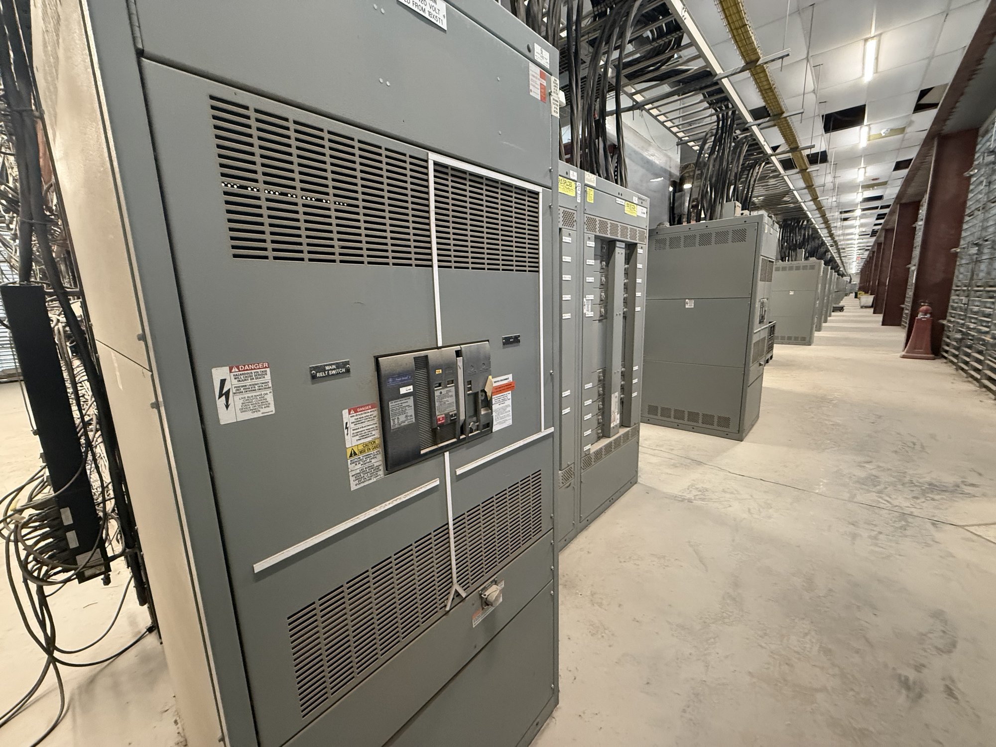
Define the power path
Start with the one-line diagram and identify the path from the incoming source through the primary equipment, transformer, and secondary distribution. Confirm system voltages, phase and frequency, grounding method, source conditions, and the intended secondary service. These details shape equipment selection and determine which interfaces require close coordination.
Clarify whether the primary section will receive utility or facility power, and whether the assembly is indoors or outdoors. Share available fault-current information, protection requirements, metering needs, and the expected operating arrangement. The design team can use these project inputs to develop a configuration for review; the final design and ratings depend on engineering and approval by the authority having jurisdiction.
Coordinate primary equipment and transformer
The primary section may include switching and protective devices suited to the incoming circuit and the transformer connection. Specify the required switching arrangement, protective functions, control power, metering, and cable or bus entry direction. Also identify whether primary conductors will approach from above, below, or a side, since entry location affects enclosure layout and field routing.
At the transformer interface, establish the connection method and the physical relationship between the primary equipment and transformer. Depending on the design, the connection may use a bus connection or cable connection; required clearances, termination space, phase arrangement, and access must be coordinated. Provide the transformer’s electrical data, construction requirements, and any specified accessories so the equipment interfaces can be evaluated together rather than treated as independent packages.
Match transformer output to the lineup
The transformer secondary must align with the distribution lineup’s voltage, phase, conductor arrangement, and grounding provisions. Confirm the intended secondary connection, main-device requirements, bus arrangement, and distribution sections. Load schedule, anticipated growth, and the facility’s operating needs help define the lineup, but the appropriate electrical ratings and protective-device coordination require project-specific engineering.
Discuss transformer impedance and available secondary fault current as part of the coordination process. Those values affect the evaluation of downstream equipment and protection. Share the required interrupting ratings, main and feeder device information, and any selective-coordination or arc-energy study criteria established for the project. Do not assume that a switchboard standard or component rating applies to the entire substation; confirm the standards and ratings applicable to each assembly and interface.
Resolve physical layout and access
A coupled arrangement can reduce the need for separately located equipment, but it still requires a workable installation footprint. Provide room dimensions, door and wall locations, equipment access routes, floor or housekeeping-pad information, and any restrictions on rigging or placement. Confirm the intended arrangement of primary section, transformer, and secondary lineup, including which faces need operating or maintenance access.
Account for ventilation, heat dissipation, cable bending space, and the transformer’s construction and cooling requirements. Indoor and outdoor applications can bring different enclosure and environmental needs. Identify exposure, ambient conditions, installation elevation where relevant, and any noise or space constraints. The project engineer should verify clearances, anchorage, ventilation, and other installation requirements against site conditions and applicable codes before release.
Specify controls, interfaces, and scope
List required interlocks, status indications, alarms, control wiring, metering, and communication points across the primary equipment, transformer, and secondary lineup. State which signals must be available to a facility control system and identify the intended interface, if known. Clear responsibility for control power, wiring between sections, and field connections helps prevent gaps between equipment supply and site installation.
For a quote, provide the one-line diagram, equipment schedule, transformer data, available fault-current information, primary and secondary connection preferences, layout drawings, and project specifications. Include required submittal documents, inspection or witness requirements, and the planned delivery location. If some inputs remain preliminary, identify them and note who will confirm them before design approval.
Plan procurement through Georgia delivery
A coordinated unit substation is a project-specific assembly, so procurement depends on configuration, component availability, design review, and the completeness of the project information. American-made components, custom-built configurations, and short lead times may be considered where they fit the specified scope; exact availability and schedule are confirmed for each order. UL 891 applies to switchboard assemblies where applicable, not as a blanket certification for every part of a substation.
For a Georgia project, align delivery planning with the site’s receiving hours, unloading equipment, access route, storage conditions, and installation sequence. Nationwide shipping can support delivery to the project location, with shipment details confirmed for the order. Before releasing the equipment, ask the project team to verify interface drawings, connection points, ratings, and responsibility for field wiring. Send the one-line diagram, transformer requirements, site layout, and delivery constraints with the quote request so the proposed assembly can be coordinated around the actual project.