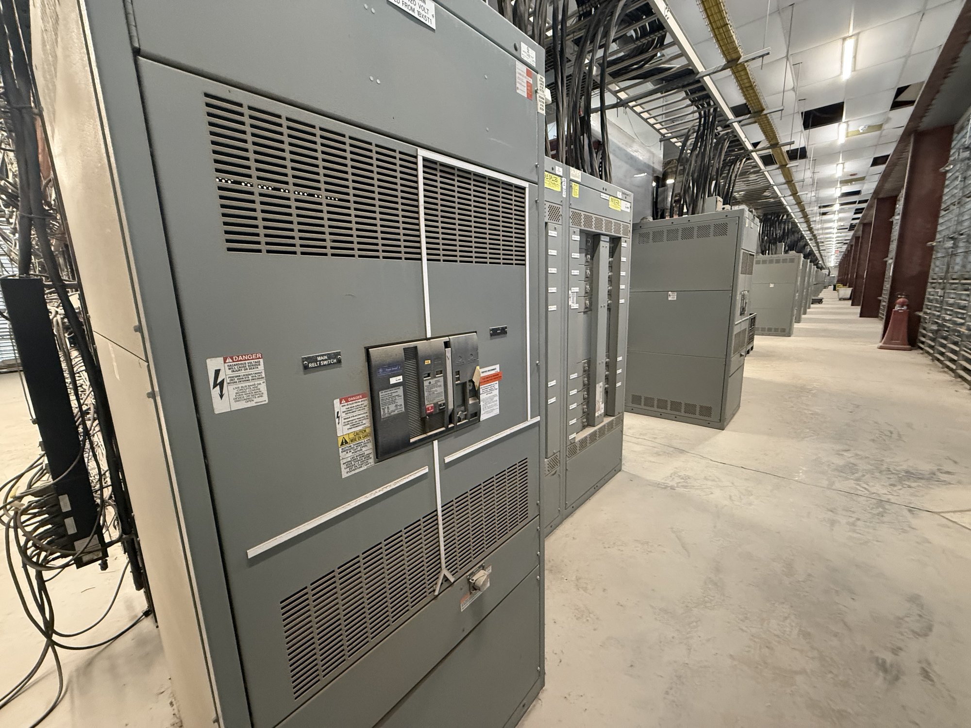
Define the permitted operating states
Start with the one-line diagram and a written sequence of operation. Identify each normal and alternate source, tie or transfer breaker, bypass switch, and load section. Then state which devices may be closed at the same time, which must be open before another can close, and whether any operating state is intentionally allowed for maintenance or testing.
A common objective is to prevent unintended paralleling of independent sources, but that is not the only possible restriction. A scheme may also prevent a tie from closing until a source breaker is open, or block transfer when a required disconnect is not in the proper position. The engineer should define the prohibited combinations and the conditions that permit each transition; equipment selection follows from that logic.
Mechanical interlocks and their limits
A mechanical interlock physically constrains operation through linkages, trapped-key arrangements, or other purpose-designed mechanisms. Depending on the equipment and arrangement, it can make one operating handle or key unavailable until another device reaches a required position. This can provide a direct barrier against a specified sequence, including when control power is absent.
Mechanical schemes depend on compatible devices, reachable operating mechanisms, and a clearly defined key or linkage sequence. They do not automatically establish that the electrical source is healthy, that voltage is absent, or that a remote device has changed state. Specify the exact devices to be interlocked, the required state indication, and any maintenance or emergency operation that must remain possible. Engineering review must confirm that the selected mechanism suits the equipment and intended operation.
Electrical interlocking and control logic
Electrical interlocking uses auxiliary contacts, relays, control wiring, and, where specified, a controller or transfer control system to permit or inhibit a command. For example, a close circuit can be conditioned on an open-position contact from another breaker. The sequence can also incorporate source-available signals, time delays, operator selection, or alarms when those functions are part of the approved design.
The logic is only as dependable as its inputs, wiring, and defined failure behavior. Ask what happens after loss of control power, a failed or contradictory position indication, a blown control fuse, or a communications interruption. Decide whether transfer is open-transition, closed-transition, manual, automatic, or a combination, and document any synchronism-check or utility coordination requirements for a scheme that could momentarily parallel sources. Do not assume an interlock alone provides protection against every electrical hazard.
Coordinate devices, drawings, and ratings
For a custom-built assembly, interlock details must align with breaker or switch type, operator arrangement, control voltage, auxiliary-contact availability, and the physical layout. The single-line diagram should match the control schematic and sequence narrative. Device designations should remain consistent across drawings, labels, operating instructions, and any project-specific test documentation so the intended permissives can be traced.
Identify the system voltage, available fault-current information, continuous-current requirements, source arrangement, and applicable project specifications for equipment selection and engineering review. UL 891 applies to switchboard assemblies; it is not a blanket listing for medium- or high-voltage switchgear. Confirm the assembly scope and applicable standards for the actual equipment rather than extending a standard beyond its scope. Ratings, certification scope, and authority acceptance require project-specific confirmation.
Prepare a useful purchase specification
When requesting a quote, provide the latest one-line diagram, source and tie details, a device schedule, and a plain-language operating sequence. Mark every combination that must be prevented and every permitted transition, including maintenance bypasses, test positions, and manual fallback if applicable. Include control-power source and voltage, desired indications and alarms, remote-control interfaces, and any utility or facility requirements that affect transfer behavior.
Also identify whether the project is new construction, a replacement, or an expansion; note enclosure and installation constraints, interface points, drawing or submittal requirements, and the desired delivery destination in Georgia. Flag open engineering decisions rather than assuming a standard scheme. Exact configuration, component availability, and timeline are confirmed for each order; a complete information package helps define scope without implying that a particular design is already available or suitable.
Verify the handoff and delivery plan
Before release, review the proposed sequence against the one-line and control drawings with the responsible electrical engineer and project team. Resolve how each permissive is established, how operators identify device position, and how the scheme behaves during abnormal conditions. Define required factory documentation and project testing expectations in the specification, while leaving installation, commissioning, and switching to qualified personnel under the applicable procedures and authority review.
For Georgia projects, coordinate the delivery destination, site access, receiving hours, unloading responsibility, and required arrival window with the project schedule. Nationwide shipping can support delivery planning, but shipment timing and order scope are confirmed individually. The practical next step is to send the diagrams, operating sequence, prohibited combinations, and site constraints together, then review the engineered interlock scheme before approving the equipment configuration.