Set the temporary-load boundary
Start by identifying which loads must remain energized, which can be shut down, and for how long. Separate essential process equipment, life-safety systems, controls and building services from loads that can be staged or deferred. Record normal and starting demand, voltage, phase, frequency, power factor where known, and any load steps that could affect a temporary source. Demand history can help, but confirm assumptions against the operating plan and equipment data.
Compare the required load with the temporary source’s usable capacity, not just its nameplate rating. Account for motor starting, transformer inrush, nonlinear loads, ambient conditions, altitude where applicable, and load growth during the outage. Decide whether temporary power will serve the entire facility or selected panels and feeders. This boundary affects the replacement switchboard configuration, temporary connection points and the number and sequence of transfers.
Define the source and connection
A temporary source may be a rental generator, an existing alternate feed or another engineered supply. Specify its electrical characteristics and available fault current, along with the connection location, cable route, connector or termination requirements, and physical access constraints. Confirm whether the temporary source is separately derived and how its neutral is configured. These details influence switching, grounding and protective-device coordination; they should be settled with the responsible electrical engineer rather than inferred from a generic generator arrangement.
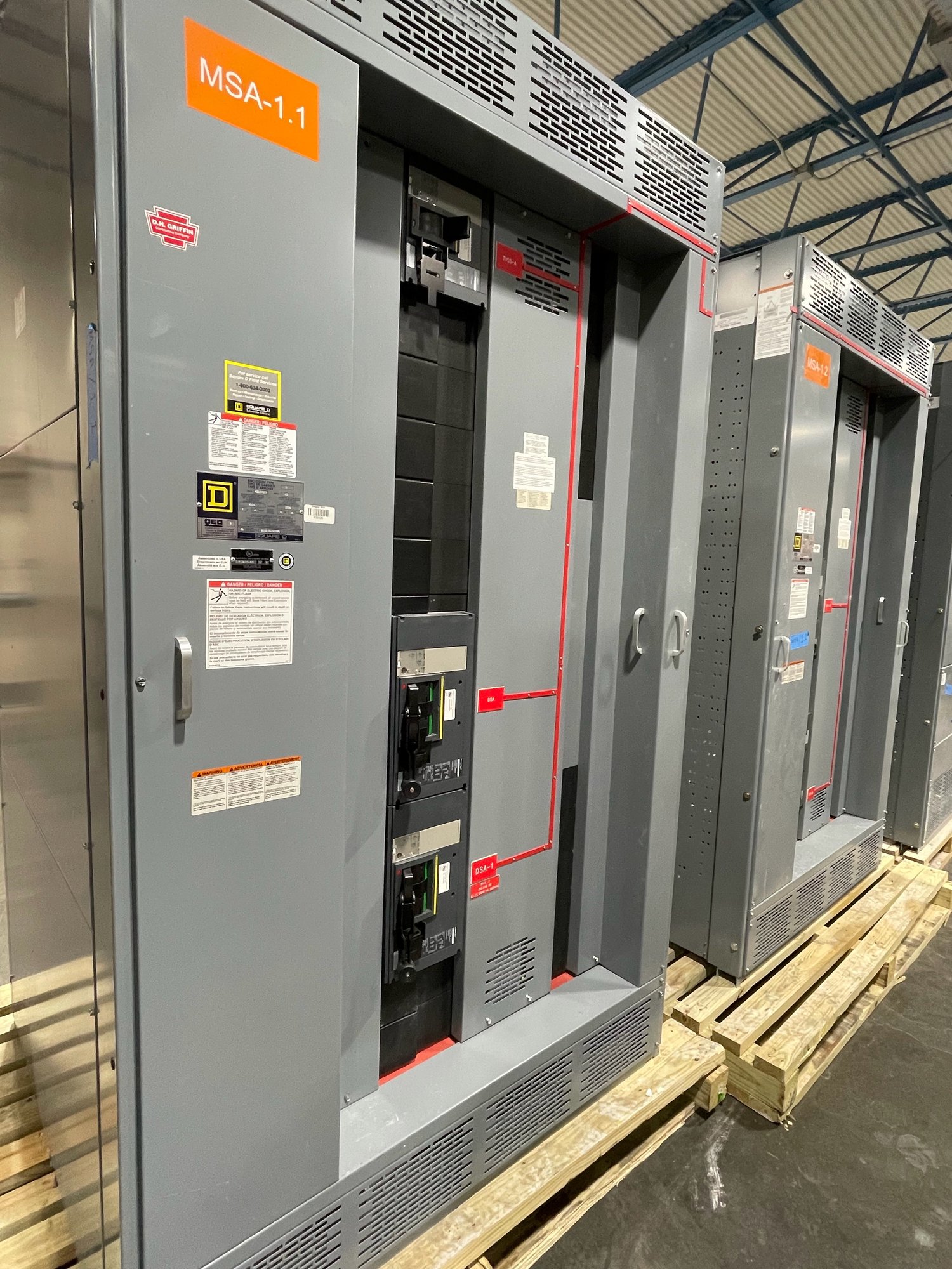
Provide drawings or field-verified information for the existing service, distribution equipment and proposed temporary tie-in. Note available space, working clearances, cable entry direction, environmental exposure, vehicle access and any restrictions on routing across operating areas. For a replacement UL 891 switchboard assembly, identify the intended service and distribution arrangement and the temporary interface that must be retained or removed. UL 891 applies to switchboards; it does not establish a listing for medium- or high-voltage switchgear.
Plan switching and cutover steps
Map each transfer from normal source to temporary source and back, including the devices that will be opened, closed, isolated and verified. The sequence must prevent unintended paralleling or backfeed unless the system is specifically engineered and authorized for parallel operation. Identify who controls each switching step, how the operating state will be confirmed, and what conditions require stopping the sequence. A one-line diagram marked with temporary connections is a useful basis for review and field coordination.
Define the outage window, load-restoration priorities and contingency if the temporary source trips or a transfer cannot proceed. Consider whether loads can be moved in stages, whether controls require an uninterrupted supply, and how operators will distinguish temporary from permanent circuits. Switching procedures and protective-device settings belong to qualified personnel under the project’s approved plan. Coordinate the replacement lineup’s delivery and installation sequence with the contractor’s outage schedule rather than assuming equipment arrival alone determines the cutover date.
Coordinate protection and grounding
Protection needs review at every operating condition: existing supply, temporary source and final configuration. A generator’s fault-current contribution may differ significantly from the utility source, affecting overcurrent-device operation and coordination. Share source data, transformer information, conductor lengths and sizes, device types and settings, and expected operating modes with the engineer performing the study. Confirm whether temporary protection is furnished as part of the source, connection equipment or distribution assembly, and define responsibility for settings and verification.
Grounding and bonding must be addressed for the temporary source, feeder conductors, equipment enclosures and existing grounding system. Clarify neutral switching, the system bonding point, and how the temporary arrangement connects to the facility grounding electrode system. Avoid relying on cable color or a familiar field arrangement as proof of a correct connection. The engineer should review the actual topology, applicable requirements and authority feedback; qualified personnel must install, test and energize the system under approved procedures.
Specify the replacement and handoff
For a manufacturer quote, provide the existing one-line, equipment photographs or schedules, system voltage and phase, service configuration, main and feeder requirements, available fault-current information, and the intended temporary-power boundary. Include the source type and ratings, connection method, grounding approach, required transfer sequence, physical constraints and requested outage milestones. Identify which items are part of the new switchboard scope and which are furnished or completed by others. Engineering review may identify missing data before configuration is finalized.
For Georgia projects, share the delivery site, receiving access, unloading constraints, installation sequence and the date the equipment must be available for the planned cutover. Exact configuration, component availability and delivery timing are confirmed for each order; do not build an outage plan around an unverified date. Before releasing the replacement design, have the project engineer and contractor reconcile the temporary connection, protection, grounding and switching documents. That coordinated package gives field teams a clear basis for installation, testing, transfer and removal of temporary equipment.