Map the power path before selecting equipment
Start by documenting every source and the loads each source must support: utility service, generator sources, UPS equipment, rectifiers, and downstream distribution. Identify which loads are essential, which may be shed, and which require uninterrupted power during transfer. Network equipment, HVAC, fire protection, security, and battery-room auxiliaries can have different priorities and restart requirements.
A one-line diagram should show normal and alternate paths, tie points, protective devices, and the intended isolation boundaries. Confirm service voltage, phase, frequency, available fault current, grounding method, and the project’s required equipment ratings with the electrical engineer and utility. These inputs determine whether the scope is a switchboard, other switchgear, or a coordinated combination; UL 891 applies to switchboard assemblies, not as a general certification for every type of switchgear.
Define source transfer and operating states
Specify how the facility should behave when utility power fails, returns, or becomes unsuitable. Transfer may be open transition, which disconnects one source before connecting another, or another engineered arrangement permitted by the system design. State whether transfer is automatic or operator initiated, what conditions initiate it, and how retransfer should occur after utility power stabilizes.
For each operating state, clarify interlocking, source supervision, and control-power requirements. The engineer should establish whether parallel operation is allowed, how inadvertent paralleling is prevented where it is not, and what happens if a generator fails to start or an alternate source is unavailable. Provide control schematics or functional sequences when available so the equipment scope can match the intended logic rather than assume a standard sequence.
Coordinate generators with facility loads
Backup generation is useful only when its capacity and response align with the loads it must carry. Share generator ratings, starting and loading characteristics, neutral and grounding details, protective-device information, and any load-shedding sequence. Discuss large motor starts, cooling equipment, UPS input behavior, and rectifier loads with the design team; their combined effects can influence generator sizing and transfer settings.
Clarify whether the switchgear scope includes generator connection points, transfer equipment, distribution breakers, metering, or control interfaces, and identify work assigned to others. Confirm the required number of sources and whether future generator additions are planned. Equipment layout must also allow for cable entry, bend space, working access, ventilation, and the facility’s available electrical-room footprint.
Keep the DC plant interface explicit
Telecommunications DC power plants commonly use rectifiers and battery strings to support designated loads, but the DC plant is a distinct system from the AC switchgear. Show where AC distribution feeds rectifiers and other plant auxiliaries, and identify which equipment provides battery charging, DC distribution, alarms, and battery disconnects. Do not assume an AC switchboard includes DC buswork or battery controls unless the project scope specifically defines them.
Ask the DC power-system designer to provide input voltage, branch loads, fault and protection requirements, grounding or bonding approach, monitoring interfaces, and any essential-versus-nonessential load distinctions. Confirm how rectifier capacity and battery autonomy are established by the project. These details help prevent gaps at the AC-to-DC boundary, where connection responsibilities, alarms, and commissioning steps can otherwise be unclear.
Specify for continuity, maintenance, and expansion
Uptime requirements should translate into testable operating criteria, not just a general preference for reliability. State which loads must remain energized during maintenance, acceptable interruption for each load group, required redundancy, and the planned response to a failed breaker or source. Engineering review should address selective coordination, arc-flash analysis, protective-device settings, and applicable codes and authority requirements; equipment configuration alone cannot establish compliance.
Discuss maintainability and future capacity early. Identify spare breaker provisions, reserved space, metering and communications needs, remote indication or control interfaces, and any limitations on shutdown windows. Specify environmental conditions, including ambient temperature, humidity, dust, and site altitude when relevant. Engineering should review these factors alongside equipment ratings and the installation layout.
Prepare the quote and Georgia project handoff
For a useful quotation, provide the latest one-line diagram, load schedule, source and generator data, transfer sequence, equipment ratings, room dimensions, cable-entry preferences, and required control or monitoring interfaces. Note the project phase, requested submittal information, delivery destination in Georgia, and any site access or receiving constraints. Identify open design decisions rather than treating assumptions as approved requirements.
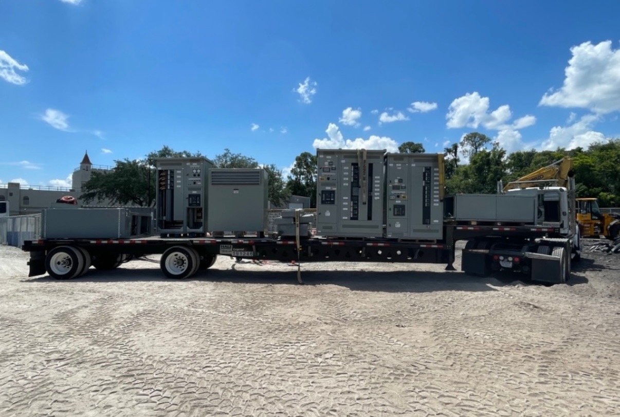
We build new switchgear and UL 891 switchboard assemblies in the United States, with custom configurations and nationwide shipping. American-made components and short lead times are priorities, but exact scope, component availability, and schedule are confirmed for each order. Before release, align approved drawings, protection and control responsibilities, utility coordination, installation scope, and commissioning expectations among the engineer, contractor, facility team, and equipment supplier. Share those project inputs to define a source-transfer and power-interface package that fits the telecommunications facility.