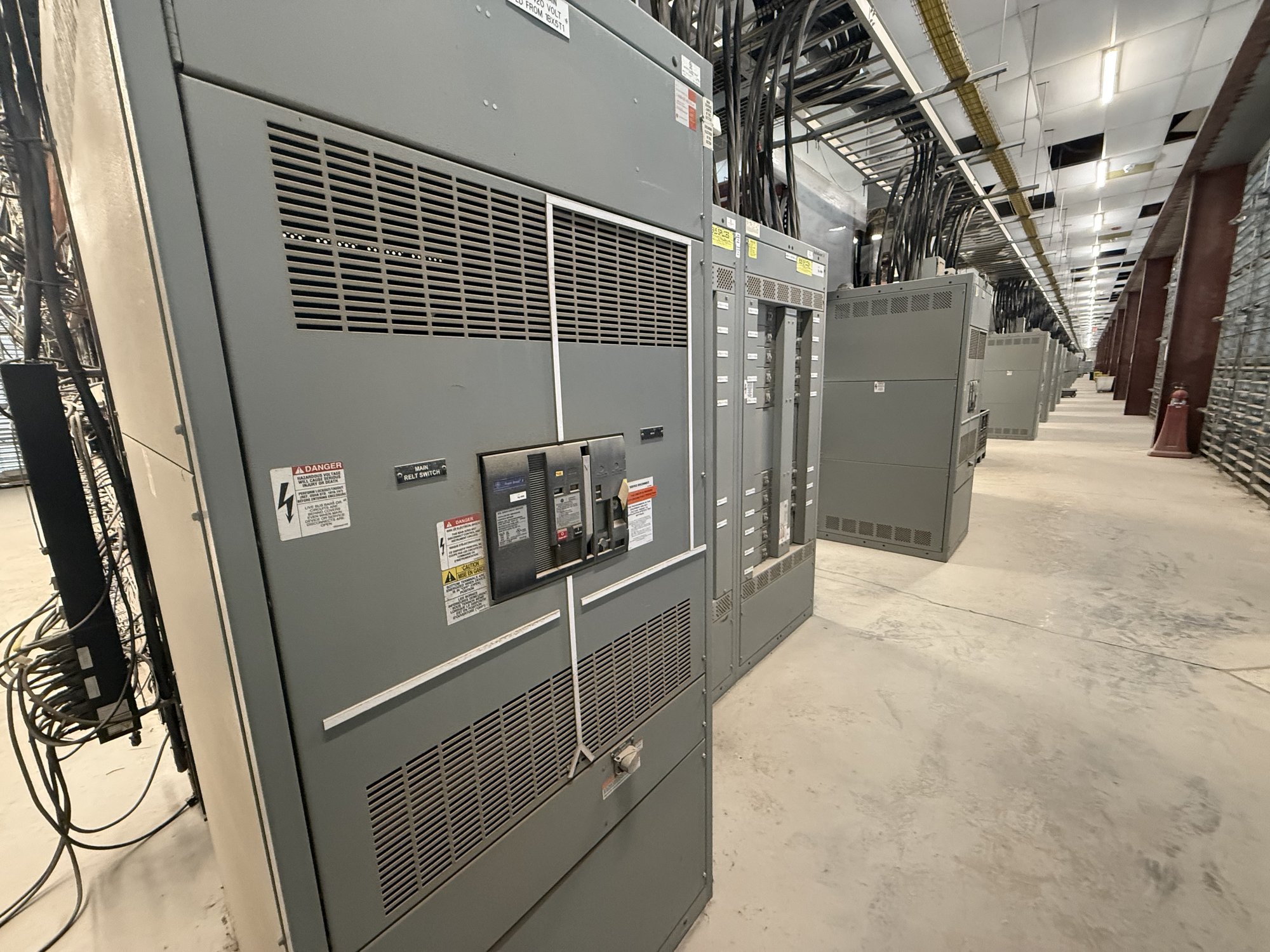
Map process loads before selecting equipment
Start with the electrical one-line and a load schedule that distinguish process tools from facility systems. Lithography, deposition, etch, metrology, vacuum pumps, chillers, exhaust, ultrapure water, and cleanroom air handling may have different operating profiles and supply requirements. Identify continuous loads, intermittent demand, planned tool additions, and loads that cannot tolerate an unplanned interruption. The applicable voltage, fault duty, feeder arrangement, and switching scheme must come from the project engineer’s design basis.
For procurement, clarify which loads are served by each board and what interfaces the assembly must accommodate. Share system voltage, phase and wire configuration, available fault-current information, main and feeder device requirements, bus arrangement, enclosure and access constraints, and any specified metering or communications provisions. These details help establish a buildable scope; final equipment selection and protection coordination remain subject to engineering review and approval by the authority having jurisdiction.
Treat continuity as a distribution-design question
High reliability depends on the complete distribution architecture, not a switchboard alone. Engineers may evaluate alternate sources, sectionalized buses, selective coordination, maintenance access, and how critical process loads respond to source transfers. A tool’s ride-through limits, upstream utility characteristics, and the facility’s backup-power strategy all affect what arrangement is appropriate. Document which loads require continuity and the acceptable operating sequence instead of assuming every process has the same interruption tolerance.
When requesting an assembly, identify required mains, ties, feeder counts, spare positions, interlocks, and provisions for future circuit additions. State whether the project calls for drawout or fixed devices, specific protective-device families, or defined control interfaces; these are project requirements to confirm, not assumptions about availability. Provide fault-current and coordination-study inputs when available, and identify any settings or labels that must be completed or verified by the responsible engineering team.
Plan monitoring around useful decisions
Monitoring is most valuable when it answers an operating question. Facilities teams may need to see feeder loading, demand trends, voltage conditions, power quality events, breaker status, or alarms associated with critical process areas. Decide which measurements belong at the main, tie, and selected feeder levels, and define who will use the data for troubleshooting, capacity planning, or maintenance. Monitoring scope should follow the facility’s instrumentation and controls architecture.
Specify required meters, communications protocols, network interfaces, alarm points, and data ownership at the outset. Confirm whether the assembly needs provisions for customer-supplied devices or defined control wiring, and provide interface drawings or points lists for coordination. Metering and communications features are not implied by a general request for switchgear; the quotation should distinguish supplied equipment from field integration, programming, and commissioning responsibilities.
Make expansion a documented phase
Semiconductor capacity often grows in stages as process areas and tool sets are added. A practical expansion plan distinguishes installed load from reserved capacity and identifies where future feeders, bus extensions, or additional distribution sections may fit. Reserve space alone does not establish electrical capacity: bus ratings, upstream source capability, protective-device coordination, room clearances, and future fault-current levels all need evaluation as the design develops.
For an initial order, share the current phase and the credible next-phase requirements, including expected circuit counts, load changes, anticipated source changes, and the date or sequence when additions may occur. Ask the project engineer to define which provisions should be installed now and which are only future design intent. This lets procurement compare a right-sized initial build with planned expansion provisions without treating a later phase as guaranteed to match today’s assumptions.
Coordinate fabrication and Georgia delivery
A clear handoff reduces late changes between design, purchasing, construction, and operations. Provide the current one-line, panel or feeder schedules, equipment specifications, room layout, cable-entry preferences, and project revision status. Flag site restrictions such as access routes, installation sequence, unloading arrangements, and required delivery windows. We build new equipment in the United States, use American-made components where specified and available, and ship nationwide; exact configuration, component availability, and delivery timing are confirmed for each order.
For a Georgia project, coordinate delivery with the construction schedule and the site’s receiving plan rather than assuming a particular local presence or fixed transit time. Before release, align the approved drawings, device schedule, nameplate data, shipping splits, and documentation requirements among the engineer, contractor, and purchasing team. UL 891 applies to switchboard assemblies when specified and applicable; it does not establish coverage for medium- or high-voltage switchgear.
Prepare a quote package that supports the build
A useful quote request answers what the equipment must serve, how it connects, and what must be ready for future phases. Include the project location in Georgia, required-by date, voltage and fault-duty basis, one-line diagram, quantity and section layout, main and feeder requirements, monitoring scope, enclosure conditions, and any specified standards or drawing milestones. Identify open engineering decisions and note whether the request covers a complete assembly or defined sections.
Also share procurement constraints such as approved submittal dates, phased release needs, shipping sequence, and the party responsible for field connections and startup. We can review the stated scope and confirm configuration, availability, and schedule for the order; the project’s qualified electrical professionals must verify design suitability, installation, protection settings, and authorization to energize. Assemble the latest design documents and phase assumptions first, then request a quote against that defined package.